Squirrel-Cage Motors
The most common form of induction motor is the squirrel-cage type . This motor has derived its name from the fact that the rotor, or secondary, resembles the wheel of a squirrel cage. Its universal use lies in its mechanical simplicity, its ruggedness, and the fact that it can be manufactured with characteristics to suit most industrial requirements.
CONSTRUCTION
A squirrel-cage motor consists essentially of two units, namely:
1. Stator,
2. Rotor.
The stator (or primary) consists of a laminated sheet-steel core with slots in which the insulated coils are placed. The coils are so grouped and connected as to form a definite polar area and to produce a rotating magnetic field when connected to a polyphase alternating-current cir cuit.
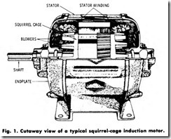
The rotor (or secondary) is also constructed of steel laminations, but the windings consist of conductor bars placed approximately parallel to the shaft and close to the rotor surface. These windings are short-cir cuited, or connected together at each end of the rotor, by a solid ring. The rotors of large motors have bars and rings of copper connected together at each end by a conducting end ring made of copper or brass. The joints between the bars and end rings are usually electrically welded into one unit, with blowers mounted on each end of the rotor. In small squirrel-cage rotors, the bars, end rings, and blowers are of aluminum cast in one piece instead of welded together.
The air gap between the rotor and stator must be very small in order for the best power factor to be obtained. The shaft must, therefore, be very rigid and be furnished with the highest grade of bearings, being usually of the sleeve or ball-bearing type. A cutaway view of a typical squirrel-cage induction motor is shown in Fig. 1.
OPERATING PRINCIPLES
In a squirrel-cage motor, the secondary, or squirrel-cage, winding takes the place of the field winding in a synchronous motor. As in a synchronous motor, the currents in the stator set up a rotating magnetic field. This field is produced by the increasing and decreasing currents in the windings. When the current increases in the first phase, only the first winding produces a magnetic field. As the current decreases in this winding and increases in the second, the magnetic field shifts slightly, until it is all produced by the second winding. When the third winding has maximum current flowing in it, the field is shifted a little more. The windings are so distributed that this shifting is uniform and continuous. It is this action which produces a rotating magnetic field.As this field rotates, it cuts the squirrel-cage conductors, and voltages are set up in these just as though the conductors were cutting the field in a de generator. These voltages cause currents to flow in the squirrel cage circuit-through the bars under the north poles into the end ring, back through the bars under the adjacent south poles into the other end ring, and back to the original bars under the north poles to complete the circuit.
The current flowing in the squirrel cage, down one group of bars and back in the adjacent group, makes a loop which establishes magnetic fields in the rotor core with north and south poles. This loop consists of one turn, but the.re are several conductors in parallel and the currents may be large. The poles in the rotor are attracted by the poles of the rotating field set up by the currents in the armature winding, and follow them around in a manner similar to the way in which the field poles follow the armature poles in a synchronous motor.
There is, however, one interesting and important difference between the synchronous motor and the induction motor-the rotor of the latter does not rotate as fast as the rotating field in the armature. If the squirrel cage were to go as fast as the rotating field, the conductors in it would be standing still with respect to the rotating field, rather than cutting across the field. Then there could be no voltage induced in the squirrel cage, no currents in it, no magnetic poles set up in the rotor, and no attraction between it and the rotating field in the stator.
SPEED
The speed of a squirrel-cage induction motor is nearly constant under normal load and voltage conditions, but is dependent on the number of poles and the frequency of the ac source. This type of motor slows down, however, when loaded an amount that is just sufficient to produce the increased current needed to meet the required torque.
The difference in speed for any given load between synchronous and load speed is called the slip of the motor. Slip is usually expressed as a percentage of the synchronous speed. Since the amount of slip is dependent on the load, the greater the load, the greater the slip will be; that is, the slower the motor will run. This slowing down of the motor, however, is very slight, even at full load, and amounts to from 1 to 4 percent of synchronous speed. Thus, the squirrel-cage type is consid ered to be a constant-speed motor.
The slip of an induction motor, as previously defined, is the dif ference between its synchronous speed and its operating speed and may be expressed in the following manner:
1. As a percentage of synchronous speed,
2. As a decimal fraction of synchronous speed,
3. Directly in revolutions per minute.
The most common method used for speed calculation of induction motors is by the use of the formula:
The synchronous speed of a motor is found by the following:
Era1np/e-A three-phase squirrel-cage induction motor having four poles is operating on a 60-hertz ac circuit at a speed of 1728 r/min. What is the slip of this motor?
Solution-By substituting the values in the previous formulas:
From the foregoing it follows that this type of motor is not suitable in industrial applications where a great amount of speed regulation is required, because the speed can be controlled only by a change in frequency, number of poles, or slip. Speed is seldom changed by changing the frequency. The number of poles is sometimes changed either by using two or more distinct windings or by reconnecting the same winding for a different number of poles.
TORQUE
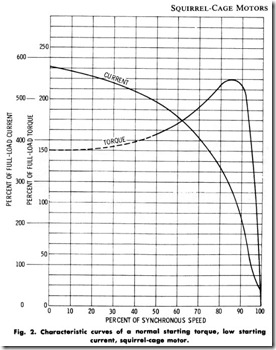
The starting torque of a squirrel-cage induction motor is the turning effort or torque which the motor exerts when full voltage is applied to its terminals at the instant of starting. The amount of starting torque which a given motor develops depends, within certain limits, on the resistance of the rotor winding. Starting torque is usually expressed as a percent of full-load torque. An increase of rotor resistance gives an increase in starting torque, with a corresponding increase in slip and a decrease in efficiency. In fact, all the desirable characteristics are so interrelated that it is impossible to make one of them surpassingly good without adversely affecting the others. Fig. 2 shows the characteristic curves of one type of squirrel-cage motor.
Motors can be built for high efficiency alone, for high starting torque, or high power factor, but there is a commercial limit which prohibits a motor from excelling in all characteristics. In order to have a basis for normal starting torques, The National Electrical Manufacturers Associ ation (NEMA) has established minimum values for motors from 2 poles to 16 poles, inclusive. With full rated voltage applied at the instant of starting, the starting torque will not be less than those listed in Table 1.
Table 1. Minimum Starting Torques for Squirrel-Cage Motors
|
No. of Poles |
Percent of Full-Load Torque |
|
2 |
150 |
|
4 |
150 |
|
6 |
135 |
|
8 |
125 |
|
10 |
120 |
|
12 |
115 |
|
14 |
110 |
|
16 |
105 |
CLASSIFICATION
Squirrel-cage motors are further classified by NEMA according to their electrical characteristics, as follows
Class A-Normal torque, normal starting-current motors.
Class B-Normal torque, low starting-current motors.
Class C-High torque, low starting-current motors.
Class D-High-slip motors.
Class E-Low starting-torque, normal starting-current motors.
Class F-Low starting-torque, low starting-current motors.
Class-A Motors
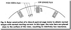
The Class-A motor is the most popular, employing a squirrel-cage winding having relatively low resistance and reactance (Fig. 3). It has a normal starting torque and low slip at the rated load, and may have sufficiently high starting current to require, in most cases, a compensa tor or resistance starter for motors above 7 1/2 hp (5.595 kW).
Class-B Motors
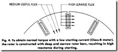
Class- B motors are built (Fig. 4) to develop normal starting torque with relatively low starting current, and can be started at full voltage. The low starting current is obtained by the design of the motor to include inherently high reactance. The combined effect of induction and frequency on the current is termed inductive reactance. The slip at rated loads is relatively low.
Class-C Motors
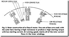
Class-C motors are usually equipped with a double squirrel-cage winding, and combine high starting torque with a low starting current. These motors can be started at full voltage. The low starting current is obtained by design (Fig. 5) to include inherently high reactance. The slip at rated load is relatively low.
Class-D Motors
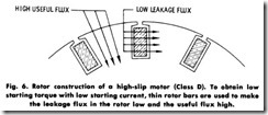
Class-D motors are provided with a high-resistance squirrel-cage winding (Fig. 6), giving the motor a high starting torque, low starting current, high slip ( 15 to 20%), and low efficiency.
Class-E Motors
Class- E motors have a low slip at rated load. The starting current may be sufficiently high to require a compensator or resistance starter above 7 1/2 hp, (5.595 kW) (see Fig. 7).
Class-F Motors
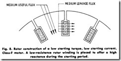
Class-F motors combine a low starting current with a low starting torque, and may be started on full voltage. The low starting current is obtained by design (Fig. 8) to include inherently high reactance.
Double Squirrel-Cage Motor
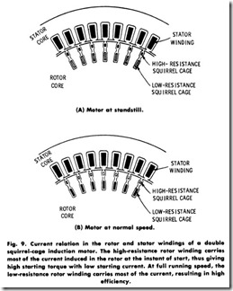
Double squirrel-cage motors are so called because they are designed with two separate squirrel-cage windings, one within the other. Thus, a motor of this type is a combination of one having both a high- and a low-resistance squirrel-cage winding. The outer cage winding is made of high-resistance material, while the inner cage winding is made of a metal having a low resistance. In starting, the high-resistance winding gives the motor a high torque, while at full-load speed the low-resis tance winding carries most of the current.
An example illustrating how the two squirrel cages operate is shown in Fig. 9. From the shape of the rotor slots, it is apparent that the bars of the inner cage are surrounded entirely by iron except for the constricted portion of the slot between the two cages, which constitutes an air gap. The bars of the outer cage are surrounded by iron at the sides only, and have two air gaps iy the magnetic path around them-that is, this path is much less perfect magnetically than that around the inner conductors. In other words, its inductance is lower.
Fig. 9A shows the condition just as the motor starts. At this instant, the rotating field produced by the stator current is sweeping across both sets of rotor conductors at the full line frequency and inducing currents in them. Since the outer conductors have a relatively low inductance, considerable current is set up, even at full line frequency. In the inner conductors, the current is greatly impeded, however, by the combined action of the higher inductance of this winding and the high frequency of the current. In fact, the choking action of the self -induction at line frequency as so great that very little current can flow through this winding at the start. The relative density of the currents in the two sets of conductors is shown by their amount of shading.
As the rotor gains in speed, the frequency of the currents induced in it decreases, and the relation between the currents in the two cages gradually and automatically changes to that shown for normal speed in Fig. 9B. For this speed, the rotor currents are proportional to the slip, and they alternate at only about one hertz. At this low frequency, the higher inductance of the inner-cage winding is of relatively little importance and produces little choking effect.
The resistance of the two cages are now the chief limiting factor in the rotor currents. Consequently, the inner, low-resistance cage carries most of the total rotor current, with the advantageous results already mentioned. The starting torque of double squirrel-cage motors is greater than that of the ordinary squirrel-cage, but less than that of a motor with a single high-resistance squirrel-cage winding.
Multispeed Squirrel-Cage Motors In certain industrial applications where two, three, or four different constant speeds are required, it is the usual practice to wind the stator with two or more separate independent windings, whose poles may be changed by changing the external connections, giving a limited number of different speeds. The speeds so obtained are always in a constant ratio, such as 1800, 1200, 900, 600, etc.
Multispeed motors can be classified into three groups according to output–constant torque, constant horsepower, and variable torque and horsepower. The relation between torque, horsepower, and speed is:
where torque is measured in pound-feet and speed in revolutions per minute.
The horsepower output of the constant-torque motor varies directly as the speed. With the constant-horsepower type, the torque is inversely proportional to the speed, the horsepower being the same at each speed. In the case of the variable-torque and horsepower type, both the horsepower and the torque decrease with a reduction in the speed. The latter motor is usually employed on loads that vary as the square or cube of the speed, such as fans and blowers, centrifugal pumps, etc. (To convert horsepower to kilowatts (kW), multiply by 0.746.)
