Circuit #2: Speed Control of a Wound Rotor Induction Motor
The second circuit to be developed will con trol the speed of a wound rotor induction motor. The motor will have three steps of speed. Separate push buttons are used to select the speed of oper ation. The motor will accelerate automatically to the speed selected. For example, if second speed is selected, the motor must start in the first or low est speed and then accelerate to second speed. If third speed is selected, the motor must start in first speed, accelerate to second speed, and then accelerate to third speed. The requirements of the circuit are as follows:
1. The motor is to operate on a 480-volt three phase power system, but the control system is to operate on 120 volts.
2. One stop button can stop the motor regard less of which speed has been selected.
3. The motor will have overload protection.
4. Three separate push buttons will select first , second, or third speed.
5. There will be a three-second time delay be tween accelerating from one speed to an other.
6. If the motor is in operation and a higher speed is desired, it can be obtained by push ing the proper button. If the motor is oper ating and a lower speed is desired, the stop button must be pressed first.
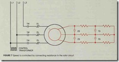
Recall that speed control for a wound rotor motor is obtained by placing resistance in the sec ondary or rotor circuit as shown in figure 7. In this circuit, load contacts 1M are used to connect the stator or primary of the motor to the power line. Two banks of three-phase resistors have been connected to the rotor. When power is applied to the stator, all resistance is connected in the rotor circuit and the motor will operate in its lowest or first speed. Second speed is obtained by closing contacts 1S and shorting out the first three-phase resistor bank. Third speed is obtained by closing contacts 2S. This shorts the rotor winding and the motor operates as a squirrel cage motor. A control transformer is connected to two of the three-phase lines to provide power for the control system.
The first speed can be obtained by connecting the circuit shown in figure 8. When the first speed button is pressed, motor starter coil 1M will close and connect the stator of the motor to the power line. Because all the resistance is in the rotor cir cuit, the motor will operate in its lowest speed.
Auxiliary contact 1M1 is used as a holding contact. A normally closed overload contact is connected in series with coil 1M to provide overload protection. Notice that only one overload contact is shown, indicating the use of a three-phase overload relay.
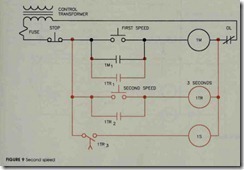
The second stage of the circuit can be seen in figure 9. When the second speed button is pressed, the coil of ON delay timer 1TR is ener gized. Since the motor must be started in the first speed position, instantaneous timer contact 1TR 1 closes to energize coil 1M and connect the stator of the motor to the line. Contact 1TR2 is used as a holding contact to keep coil 1TR energized when the second speed button is released. Contact 1TR3 is a timed contact. At the end of three seconds, it will close and energize contactor coil IS, causing all IS contacts to close and shunt the first set of resistors. The motor now operates in second speed.
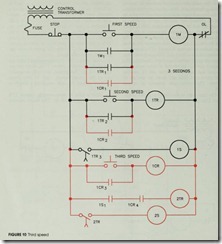
the coil of control relay 1CR. When coil 1CR is energized, all 1CR contacts change position. Con tact 1CR1 closes to provide a current path to mo tor starter coil 1M, causing the motor to start in its lowest speed. Contact 1CR2 closes to provide a current path to timer 1TR. This permits timer lTR to begin its timer operation. Contact 1CR3 maintains a current path to coil lCR after the third speed button is opened, and contact lCRt permits a current path to be established to timer 2TR. This contact is also used to prevent a cur rent path to coil 2TR when the motor is to be op erated in the second speed.
After timer 1TR has been energized for a pe riod of three seconds, contact 1TR3 closes and en ergizes coil 1S. This permits the motor to acceler ate to the second speed. Coil IS also closes auxiliary contact 1S1 and completes a circuit to timer 2TR.
After a delay of three seconds, contact 2TR closes and energizes coil 2S. This causes contacts
The final stage of the circuit is shown in fig ure 10. The third speed button is used to energize 2S to close and the motor operates in its highest speed.
Circuit #3: An Oil Heating Unit
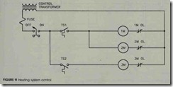
In the circuit shown in figure 11, motor starter 1M controls a motor that operates a high pressure pump. The pump is used to inject fuel oil into a combustion chamber where it is burned. Motor starter 2M operates an air induction blower that forces air into the combustion chamber when the oil is being burned. Motor starter 3M controls a squirrel cage blower which circulates air across a heat exchanger to heat a building. A control trans former is used to change the incoming voltage from 240 volts to 120 volts, and a separate OFF ON switch can be used to disconnect power from the circuit. Thermostat TS 1 senses temperature inside the building and thermostat TS2 is used to sense the temperature of the heat exchanger.
To understand the operation of the circuit, assume the manual OFF-ON switch is set in the ON position. When the temperature inside the building drops to a low enough level, thermostat TS 1 closes and provides power to starters 1M and 2M. This permits the pump motor and air induc tion blower to start. When the temperature of the heat exchanger rises to a high enough level, ther mostat TS2 closes and energizes starter 3M. The blowet;” circulates the air inside the building across the heat exchanger and raises the temperature in side the building. When the building temperature rises to a high enough level, thermostat TS1 opens and disconnects the pump motor and air induction motor. The blower will continue to operate until the heat exchanger has been cooled to a low enough temperature to permit thermostat TS3 to open its contact.
After some period of operation, it is discovered that the design of this circuit can lead to some serious safety hazards. If the overload con tact connected to starter 2M should open, the high-pressure pump motor will continue to oper ate without sufficient air being injected into the combustion chamber. Also, there is no safety switch to turn the pump motor off if the blower motor fails to provide cooling air across the heat exchanger. It is recommended that the following changes be made to the circuit:
1. If an overload occurs to the air induction motor, it will stop operation of both the high-pressure pump motor and the air induc tion motor.
2. An overload of the high pressure pump mo tor will stop only that motor and permit the air induction motor to continue operation.
3. The air induction motor will continue oper ating for one minute after the high-pressure pump motor has been turned off. This will clear the combustion chamber of excessive smoke and fumes.
4. A high-limit thermostat is added to the heat exchanger to turn the pump motor off if the temperature of the heat exchanger should be come excessive.
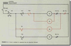
These circuit changes can be seen in figure 12. Thermostat TS3 is the high limit thermostat. Since it is to be used to perform the function of stop, it is normally closed and connected in series with motor starter 1M. An off delay timer is used to control starter 2M, and the overload contact of starter 2M has been connected in such a manner that it can stop the operation of both the air in duction blower and the high-pressure pump. No tice, however, that if 1M overload contact opens, it will not stop the operation of the air induction blower motor . The air induction blower motor would continue to operate for a period of one min ute before stopping.
The logic of the circuit is as follows: When thermosta t TS1 closes its contact, coils 1M and TR are energized. Because timer TR is an off de lay timer, contact TR closes immediately, permit ting motor starter 2M to energize. When thermo stat TS1 is satisfied and reopens its contact, or if thermostat TS3 opens its contact, coils 1M and TR will deenergize. Contact TR will remain closed for a period of one minute before opening and disconnecting starter 2M from the power line.
Although the circuit in figure 12 satisfies the basic circuit requirement, there is still a potential problem. If the air induction blower fails for some reason other than the overload contact opening, the high-pressure pump motor will continue to in ject oil into the combustion chamber. To prevent this situation, an airflow switch, FL1, is added to the circuit as shown in figure 13. This flow switch is mounted in such a position that it can sense the movement of air produced by the air induction blower.
When thermostat contact TS1 closes, coil TR energizes and closes contact TR. This provides a circuit to motor starter 2M. When the air injection blower starts, flow switch FLl closes its contact and permits the high-pressure pump motor to start. If the air injection blower motor stops for any reason, flow switch FLl will disconnect motor starter 1M from the power line and stop operation of the high-pressure pump.
Although the circuit now operates as desired, the owner of the building later decides the blower should circulate air inside the building when the heating system is not in use. To satisfy this re quest, an AUTO-MANUAL switch is added as shown in figure 14. When the switch is set in the AUTO position, it permits the blower motor to be controlled by the thermostat TS2. When the switch is set in the MANUAL position, it con nects the coil of starter 3M directly to the power line and permits the blower motor to operate in dependently of the heating system.

![FIGURE-13-An-air-flow-switch-control[1] FIGURE-13-An-air-flow-switch-control[1]](http://machineryequipmentonline.com/electric-equipment/wp-content/uploads/2020/04/FIGURE-13-An-air-flow-switch-control1_thumb.jpg)
![FIGURE-14-An-AUTO-MANUAL-switch-is-a[1] FIGURE-14-An-AUTO-MANUAL-switch-is-a[1]](http://machineryequipmentonline.com/electric-equipment/wp-content/uploads/2020/04/FIGURE-14-An-AUTO-MANUAL-switch-is-a1_thumb.jpg)