When the rotor of IMs is provided with a wound rotor, speed control is performed by
• Adding a variable resistor to the rotor circuit
• Connecting a power converter to the rotor to introduce or extract power from the rotor. Let us call this procedure additional voltage to the rotor.
As the method of additional rotor resistance has been presented for starting, it will suffice to stress here that only for limited speed control range (say 10%) and medium power such a method is still used in some special applications. In the configuration of self-adjustable resistance, it may also be used for 10 to 15% speed variation range in generators for windpower conversion systems.
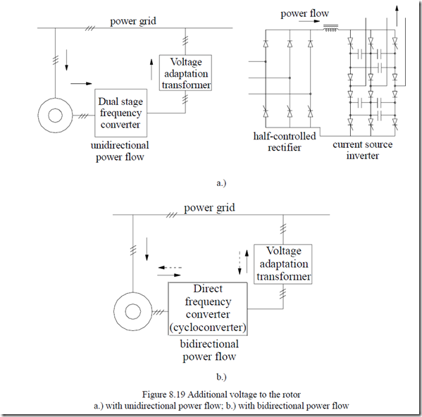
In general, for this method, a unidirectional or a bidirectional power flow frequency converter is connected to the rotor brushes while the stator winding is fed directly, through a power switch, to the power grid (Figure 8.19).
Large power motors (2-3 MW to 15 MW) or very large power generators/motors, for pump-back hydropower plants (in the hundreds of MW/unit), are typical for this method.
A half-controlled rectifier-current source inverter has constituted for a long while one of the most convenient ways to extract energy from the rotor while the speed decreases 75 to 80% of its rated value. Such a drive is called a slip recovery drive and it may work only below ideal no-load speed (S > 0). 8.5.1 Additional voltage to the rotor (the doubly-fed machine)
On the other hand, with bidirectional power flow, when the phase sequence of the voltages in the rotor may be changed, the machine may work both as a motor or as a generator, both below and above ideal no-load speed f1/p1.
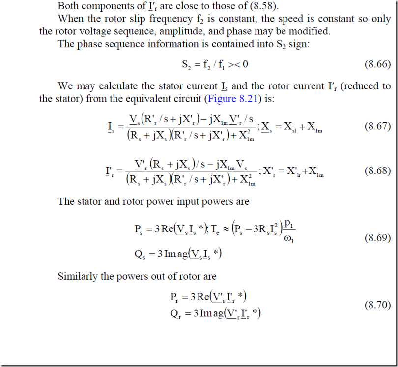
With such direct frequency converters, it is possible to keep the rotor slip frequency f2 constant and adjust the rotor voltage phase angle δ with respect to stator voltage after reduction to stator frequency.
The speed is constant under steady state and the machine behaves like a synchronous machine with the torque dependent on the power angle δ (S = f2/f1 = ct).
On the other hand, the frequency f2 may be varied with speed such that
f 2 = f1 − np ; s1 = f 2 / f1 − variable (8.50)
In this case, the phase angle δ may be kept constant. The rotor equation is
I‘r R’s r + V‘r = −jSω1 Ψ‘r = SE‘r (8.51)
For Vr in phase (or in phase oposition for V′r < 0) with E′r
I‘ R’r r = SE‘r −V‘r (8.52)
For zero rotor current, the torque is zero. This corresponds to the ideal noload speed (slip, S0)
s E’0 r −V’r = 0;s0 = V’r (8.53)
E’r
So, may be positive if V′r > 0, that is V′r and E′r are in phase while it is negative for V′r<0 or V′r or V′r and E′r in phase opposition.
For constant values of V′r (+ or – ), the torque speed curves obtained by solving the equivalent circuit may be calculated as
Te = PSelmωp1 1 = S3ωp11 [I’ R’r2 r +V’ I’ cos ‘r r θ r ] (8.54)
θ′r is the angle between V′r and I′r. In our case, θr = 0 and V′r is positive or negative, and given.
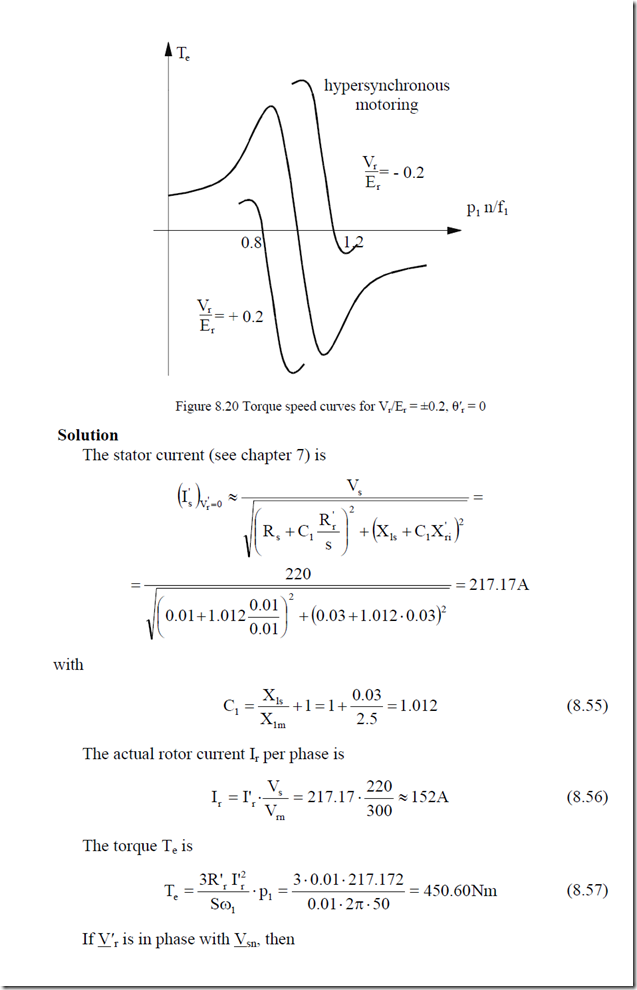
It is seen (Figure 8.20) that with such a converter, the machine works well as a motor above synchronous conventional speed f1 /p1 and as a generator below f1 /p. This is true for voltage control. A different behavior is obtained for constant rotor current control. [7]
However, under subsynchronous motor and generator modes, all are feasible with adequate control.
Example 8.4 Doubly – fed IM
An IM with wound rotor has the data: Vsn = 220 V/phase, f1 = 50 Hz, Rs =
R′s= 0.01 Ω, Xsl = X′rl = 0.03 Ω, X1m = 2.5 Ω, 2p1 = 2, Vrn = 300 V/phase, Sn =
0.01. Calculate
• the stator current and torque at sn = 0.01 for the short-circuited rotor;
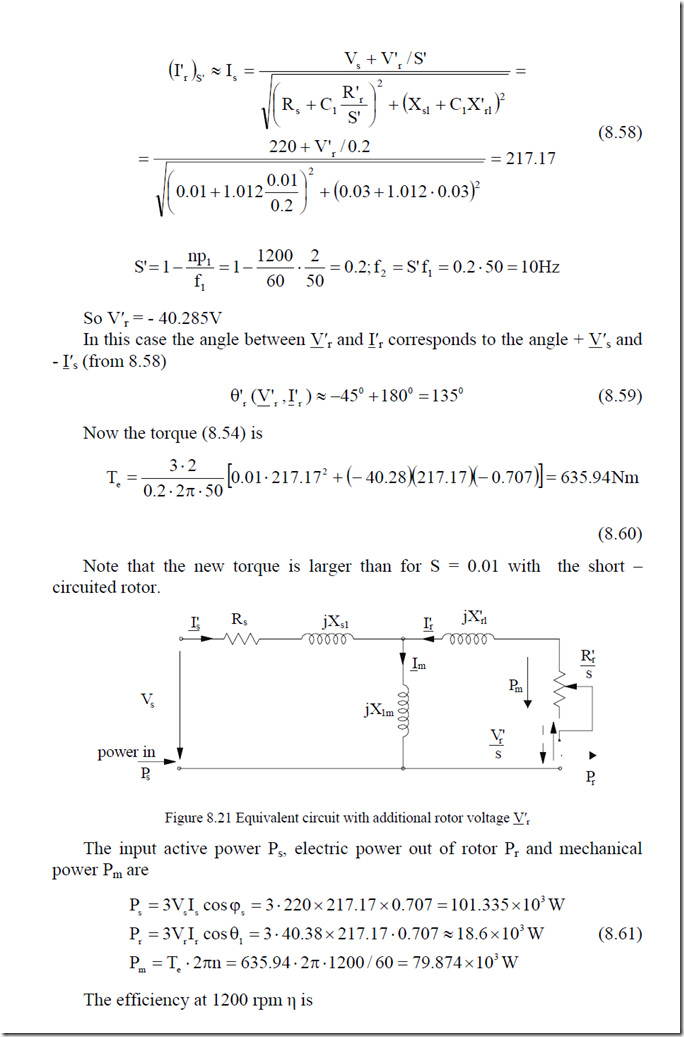
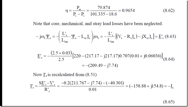
• for same stator current at n =1200 rpm calculate the rotor voltage Vr in phase with stator voltage Vsn (Figure 8.21) and the power extracted from the rotor by frequency converter.
With S = const, such a control method can work at constant rotor voltage V′r but with variable phase γ (Vs, V′r). Alternatively, it may operate at constant stator or rotor current [8,9]. Finally, vector control is also feasible. [6] Such schemes are currently proposed for powers up to 300 MW in pump-storage power plants where, both for pumping and for generating, a 10 to 25% of speed control improves the hydroturbine-pump output.
The main advantage is the limited rating of the rotor-side frequency converter S Sr = max ⋅Sn . As long as Smax < 0.2 – 0.15, the savings in converter costs are very good. Notice that resistive starting is required in such cases.
For medium and lower power limited speed control, dual stator winding stator nest cage rotor induction motors have been proposed. The two windings have different pole numbers p1, p2, and the rotor has a pole count pr = p1+p2. One winding is fed from the power grid at the frequency f1 and the other at frequency f2 from a limited power frequency converter. The machine speed n is
n = pf11 ±+ fp22 (8.71)
The smaller f2, the smaller the rating of the corresponding frequency converter. The behavior is typical to that of a synchronous machine when f2 is const. Low speed applications such as wind generators or some pump applications with low initial cost for very limited speed control range (less than 20%) might be suitable for those configurations with rather large rotor losses.
