Liquid low sensors
Liquid flow is a very important part of many manufacturing processes, and where the manufacturing process is continuous, rather than a batch process, the sensing and measurement of liquid flow is a vital part of plant control. Flow measurement is, for example, vital in the all-important water industry, both at the supply side for potable water and at the disposal side in sewage treatment works. It is equally important for milk-based industries (e.g. cheese, butter, yoghurt), in chemical works (where relative quantities of liquids entering a reaction vessel may have to be controlled and measured to fairly fine limits), and in printing.
Flow monitoring in one form or another is used in most machines to ensure that lubrication is adequate and that coolant is circulating correctly. As applied to gases, flow monitors are used in healing and air-con- ditioning plants, in air-cooling of machines and in gas-based chemical reactions. Monitoring is particularly important for both gases and liquids if a stoppage might indicate a blockage or other fault condition, such as pump failure.
The sensing of liquid flow can take three different forms. One is vector flow, in which the speed and direction of the liquid need to be sensed. Another possible requirement is volume flow, measuring the volume per second of liquid passing a point in a pipe. The third possible requirement is mass flow, which is usually calculated from volume flow using the relation- ship, mass = volume X density. For most automation requirements, with liquids confined in tubes, the volume flow is the important one.
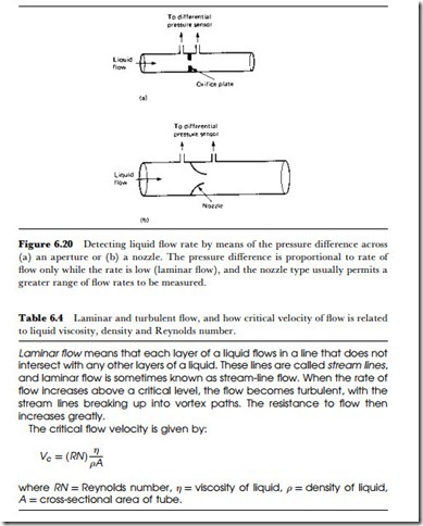
There is no simple and straightforward method of measuring liquid volume flow, although sensing flow is comparatively simple. One of the simplest methods is based on the pressure difference that occurs when the liquid flow is through an orifice, which can be an orifice plate or a nozzle (Figure 6.20). For a liquid whose flow rate is slow enough to be laminar (stream-line), as defined in Table 6.4, the pressure difference across the orifice is linearly proportional to the rate of flow. This pressure difference can be sensed or measured by a manometer or by the difference in level between two tubes. If the flow is not laminar (see Table 6.4) but is
turbulent, the pressure is more likely to be proportional to the square of liquid speed.
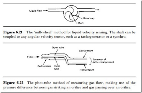
If the presence of mechanically moving parts in the liquid stream is permissible, the ‘mill-wheel’ method can be used. In this method (Figure 6.21), the movement of the liquid turns a turbine wheel which in turn is coupled to a tachometer. This method is quite acceptable for liquids whose flow rate is comparatively slow, and over a fair range of liquid velocity the
output is reasonably proportional to the flow rate. The device needs calibration, however, either from another form of gauge or by the ancient method of measuring how much liquid (volume or mass) is delivered in a given time.
Most commercially available methods of flow transducers are based on this principle, although in many processes liquid flow is monitored visually using the old-established tube-and-float method which, because it has no electrical output, is outside the scope of this book. The turbine blades need to be constructed from a material that will be resistant to the type of liquid being measured, and careful selection will be needed, because there are few materials that can be used for a wide range of chemicals. The conversion from turbine speed to electrical output is carried out typically by using a light source and photocell unit, although for some specialized applications (very dark liquids) it may be necessary to use a Hall-effect sensor and a turbine with ferrite magnets included in its vanes. Another, more crude, method uses a vane mounted on a spring-loaded shaft which is placed in the liquid flow. This senses the deflection of the vane by the angle through which the vane is turned. This angle is most simply sensed by a potentiometer connected to the shaft.
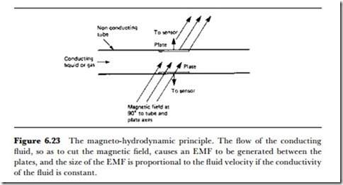
For sensing and measuring vector flow, the pitot tube is a method that has been used for some considerable time, particularly for the indication of aircraft air speed. The principle is illustrated in Figure 6.22 in its most elementary form, and consists of a liquid U-tube manometer whose two ends are both fed from nearby points. One of these points is directed at the oncoming airstream, and the other is a perforated tube over which the airstream passes. The pressure difference between these two will depend on
the speed and direction of the airstream. The pitot-tube principle can be used with gases and with liquids of low viscosity, and can be adopted for electronic sensing methods by using an electronic manometer.
A method that can be used only for conducting liquids is the magneto- hydrodynamic sensor, whose principle is illustrated in Figure 6.23. Two electrodes are in contact with the moving liquid in a tube, and a strong magnetic field is applied at right angles both to the axis of the tube and to the line joining the electrodes. Motion of the liquid will cause an EMF to be generated between the electrodes, in accordance with Faraday principles. The amplitude of the EMF is proportional to the rate at which the flux of the magnet is cut, so it is proportional to the velocity of the liquid.
The requirement for the liquid to be conducting makes this method of little use for many applications, but it can be used with ionized gases. It has had some limited application as a transducer used to generate electricity from exhaust gases of both gas turbines and coal-fired generating systems.


