Digital circuits are being used more and more in electronics, not only in computers but also in applications such as measurement, automatic control, robotics, and in situations requiring decisions. All of these applications require complex switching circuits that are formed from the five basic logic gates: the AND, OR, NAND, and NOR gates and the inverter. The significant point about these logic gates is that they only have two operating conditions. They are either ON (1) or OFF (0). When logic gates are inter- connected to form more complex circuits, it is necessary to obtain the simplest circuit possible.
Boolean algebra offers a means of expressing complex switching functions in equation form. A Boolean expression is an equation that expresses the output of a logic circuit in terms of its input. Veitch diagrams and Karnaugh maps provide a fast and easy way to reduce a logic equation to its simplest form.
Vetch Diagrams
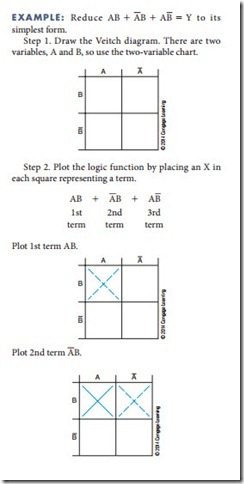
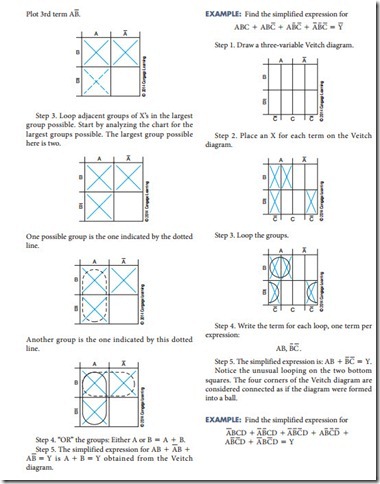
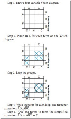
Veitch diagrams provide a fast and easy method for reducing a complicated expression to its simplest form. They can be constructed for one, two, three, or four variables. Figure 43-1 shows several Veitch diagrams.
To use a Veitch diagram, follow these steps, as illustrated in the example:
1. Draw the diagram based on the number of variables.
2. Plot the logic functions by placing an X in each square representing a term.
3. Obtain the simplified logic function by looping adjacent groups of X’s in groups of eight, four, two, or one. Continue to loop until all X’s are included in a loop.
4. “OR” the loops with one term per loop. (Each ex- pression is pulled off the Veitch diagram and “OR”ed using the 1 symbol, for example, ABC 1 BCD.)
5. Write the simplified expression.
Questions
1. What is the function of a Veitch diagram?
2. How many variables can be represented on a Veitch diagram?
3. list the steps for using a Veitch diagram.


