INDUSTRIAL MEASUREMENT SENSORS
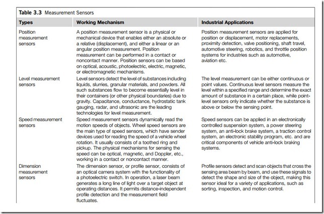
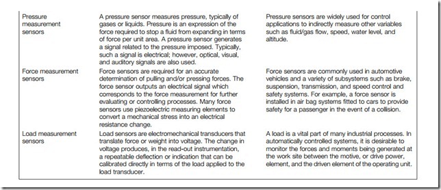
Sensors for measurement in industrial applications provide a comprehensive and practical introduction to the increasingly important topic of sensor technology, and also serves as an extensive guide to sensors and their applications. Table 3.3 gives the main types of industrial measurement sensors. Due to space restrictions, this section briefly explains only two measurement sensors; force and load sensors.
Force sensors
The most common dynamic force and acceleration detector is the piezoelectric sensor. A piezoelectric sensor produces a voltage when it is squeezed by a force. This voltage is proportional to the force applied. The fundamental difference between such devices and static force detection devices is that the electrical signal generated by the crystal decays rapidly after the application of force. This makes piezoelectric sensors unsuitable for the detection of static force.
Depending on the application requirements, dynamic force can be measured as either compressive, tensile, or torque force. Applications may include the measurement of spring or sliding friction forces, chain tensions, clutch release forces, or peel strengths of laminates, labels, and pull tabs.
The high-impedance electrical signal generated by the piezoelectric crystal is converted (by an amplifier) to a low-impedance signal suitable for such an instrument as a digital storage oscilloscope. Digital storage of the signal is required in order to allow analysis of the signal before it decays. The low-impedance voltage mode (LIVM) force sensor, discussed below, is a typical example of a piezoelectric force sensor.
A pressure sensor measures pressure, typically of gases or liquids. Pressure is an expression of the force required to stop a fluid from expanding in terms of force per unit area. A pressure sensor generates a signal related to the pressure imposed. Typically, such a signal is electrical; however, optical, visual, and auditory signals are also used.
Force sensors are required for an accurate determination of pulling and/or pressing forces. The force sensor outputs an electrical signal which corresponds to the force measurement for further evaluating or controlling processes. Many force sensors use piezoelectric measuring elements to convert a mechanical stress into an electrical resistance change.
Load sensors are electromechanical transducers that translate force or weight into voltage. The change in voltage produces, in the read-out instrumentation, a repeatable deflection or indication that can be calibrated directly in terms of the load applied to the load transducer.
Pressure sensors are widely used for control applications to indirectly measure other variables such as fluid/gas flow, speed, water level, and altitude.
Force sensors are commonly used in automotive vehicles and a variety of subsystems such as brake, suspension, transmission, and speed control and safety systems. For example, a force sensor is installed in air bag systems fitted to cars to provide safety for a passenger in the event of a collision.
A load is a vital part of many industrial processes. In automatically controlled systems, it is desirable to monitor the forces and moments being generated at the work site between the motive, or drive power, element, and the driven element of the operating unit.
(1) Construction and operating principles
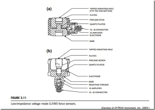
Figure 3.11(a) shows a typical LIVM force sensor with radial connector. Figure 3.11(b) shows an axial connector sensor.
Two quartz discs are preloaded together between a lower base and an upper platen by means of an elastic preload screw (or stud) as seen in Figure 3.11(a) and (b). Preloading is necessary to ensure that the crystals are held in close contact, for best linearity and to allow a tension range for the instruments. In the radial connector style (Figure 3.11(a)), both platen and base are tapped to receive threaded members such as mounting studs, impact caps or machine elements. Platen and base are welded to an outer housing which encloses and protects the crystals from the extemal environment. A thin, steel web connects the platen to the outer housing, allowing the quartz element structure to flex unimpeded by the housing structure. The integral amplifier is located in the radially mounted connector housing.
Construction of the axial connector type (Figure 3.11(b)) is similar to the radial connector type, except that the lower base contains a threaded, integral, mounting stud, which also serves as the amplifier housing, and supports the electrical connector. This design allows the electrical connection to exit axially, which is especially useful where radial space is limited.
When the crystals are stressed by an external compressive force, an analogous positive polarity voltage is generated. This voltage is collected by the electrode and connected to the input of a metal oxide silicon field effect transistor unity gain source follower amplifier located within the amplifier housing. The amplifier serves to lower the output impedance of the signal by 10 orders of magnitude, so that it can be displayed on readout instruments such as oscilloscopes, meters or recorders. When the sensor is put under tensile loads (pulled), some of the preload is released, causing the crystals to generate a negative output signal. Maximum tensile loading is limited by the ultimate strength of the internal preload screw and is usually much less than the compression range.
(2) Application guides
Because they are almost as rigid as a comparably proportioned piece of solid steel, piezoelectric force sensors may be inserted directly into machines as part of their structure. By virtue of this high rigidity, these sensors have very high natural frequencies with fast rise time capabilities, making them ideal for measuring very quick transient forces, such as those generated by metal-to-metal impacts and high- frequency vibrations.
Although LIVM force sensors are designed to measure dynamic forces, the discharge time constants of most units are long enough to allow static calibration, by which we mean the use of calibrated weights or ring dynamometers. An important rule of thumb for this type of calibration is that the first 10% of the discharge time constant curve is relatively linear with respect to time. What this means is that the output signal will decay 1% in 1% of the discharge time constant, and so on up to about 10 seconds. This tells us that, in order to make a reading that is accurate to 1% (other measurement errors not considered), we must take our reading within 1% of the discharge time constant (in seconds), after application of the calibration force.
The most convenient way to do this is by use of a digital storage oscilloscope and a DC (direct current) coupled current source power unit. The DC coupled unit is essential because the AC (alter- nating current) coupling of conventional power units would make the overall system coupling time- constant too short to perform an accurate calibration in most cases.
3.3.2 Load sensors
The most common technology used by load sensors uses the principle of strain gauges.
In a photoelectric strain gauge, a beam of light is passed through a variable slit, actuated by the extensometer, and directed to a photoelectric cell. As the gap opening changes, the amount of light reaching the cell varies, causing a matching intensity change in the current generated by the cell. Semiconductor or piezoelectric strain gauges are constructed of ferroelectric materials, such crystal- line quartz. In such materials a change in the electronic charge across the faces of the crystal occurs when it is mechanically stressed. The piezoresistive effect is defined as the change in resistance of a material due to given applied stress, and this term is commonly used in connection with semi- conducting materials. Optical strain gauge types include photoelastic, moire´ interferometer, and holographic interferometer strain gauges. In a fiber-optic strain gauge, the sensor measures the strain by shifting the frequency of the light reflected down the fiber from the Bragg grating, which is embedded inside the fiber itself.
The gauge pattern refers cumulatively to the shape of the grid, the number and orientation of the grids in a multiple grid (rosette) gauge, the solder tab configuration, and various construction features that are standard for a particular pattern. Arrangement types include uniaxial, dual linear, strip gauges, diaphragm, tee rosette, rectangular rosette, and delta rosette. Specialty applications for strain gauges include crack detection, crack propagation, extensometer, temperature measurement, residual stress, shear modulus gauge, and transducer gauge.
The three primary specifications when selecting strain gauges are operating temperature, the statistics of the strain (including gradient, magnitude, and time dependence), and the stability required by the application. The operating temperature range is the range of ambient temperature where the use of the strain gauge is permitted without permanent changes of the measurement properties. Other important parameters to consider include the active gauge length, the gauge factor, nominal resistance, and strain-sensitive material. The gauge length of a strain gauge is the active or strain-sensitive length of the grid. The end loops and solder tabs are considered insensitive to strain because of their relatively large cross-sectional area and low electrical resistance.
The strain sensitivity of a strain gauge is the ratio between the relative changes in resistance. The strain sensitivity is dimension less and is generally called the gauge factor. The resistance of a strain gauge is defined as the electrical resistance measured between the two metal ribbons or contact areas intended for the connection of measurement cables. The principal component that determines the operating characteristics of a strain gauge is the strain-sensitive material used in the foil grid.


