INDUSTRIAL ACTUATORS
Industrial actuators are categorized by energy source. This section will discuss five actuators which use different types of energy; electric, magnetic, pneumatic, hydraulic and piezoelectric actuators.
Electric actuators
Electric actuators, which use the simplicity of electrical operation, provide the most reliable means of positioning a valve in a safe condition, including a fail-safe to closed or open, or a lock in position on power or system failure. However, electric actuators are not restricted to open or close applications; with the addition of one or more of the available options, the requirements of fully fledged control units can often be met. For example, with both weatherproof and flameproof models, the range simplifies process automation by providing true electronic control from process variable to valve and supplies a totally electric system for all environments. The unit can be supplied with the appropriate electronic controls to match any process control system require- ment. More and more often, electric actuators provide a superior solution, especially when high accuracy, high duty cycle, excellent reliability, long life expectancy, and low maintenance are supplied by extra switches, speed controllers, potentiometers, position transmitters, positioners, and local control stations. These options may be added to factory-built units, or supplied in kit form. When supplied as kits, all parts are included together with an easy to follow installation sheet.
(1) Operating principle
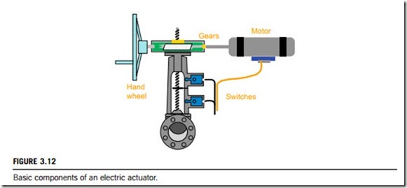
The architecture for an electric actuator is given in Figure 3.12, and consists basically of gears, a motor, and switches. In these components, the motor plays a key role. In most applications, the motor is the primary torque-generating component. Motors are available for a variety of supply voltages, including standard single-phase alternating current, three-phase and DC voltages. In some applica- tions, three-phase current for the asynchronous electric actuator is generated by means of the power circuit module, regardless of the power supply (one or three phase). Frequency converters and microcontrollers allow different speeds and precise tripping torques to be set (no over-torque). When an electric actuator is running, the phase angle is checked and automatically adjusted, so that the rotation is always correct. To prevent heat damage due to excessive current draw in a stalled condition, or due to overwork, electric actuator motors usually include a thermal overload sensor or switch embedded in the winding of the stator. The sensor or switch is installed in series with the power source, and opens the circuit when the motor is overheated, and then closes the circuit once it has cooled to a safe operating temperature.
Electric actuators rely on a gear train (a series of interconnected gears) to enhance the motor torque and to regulate the output speed of the actuator. Some gear styles are inherently self-locking. This is particularly important in the automation of butterfly valves, or when an electric actuator is used in modulating control applications. In these situations, seat and disk contact, or fluid velocity, act upon the closure element of the valve and causes a reverse force that can reverse the motor and camshaft. This causes a re-energization of the motor through the limit switch when the cam position is changed. This undesirable cycling will continue to occur unless a motor brake is installed, and usually leads to an overheated motor. Spur gears are sometimes used in rotary electric actuators, but are not self-locking. They require the addition of an electromechanical motor brake for these applications.
One self-locking gear types is a worm and wheel, with some configurations of planetary gears. A basic worm gear system operates as follows: a motor applies a force through the primary worm gear to
the worm wheel. This, in turn, rotates the secondary worm gear which applies a force to the larger radius of the secondary worm wheel to increase the torque.
(2) Basic types
Electric actuators are divided into two different types; rotary and linear. Rotary electric actuators rotate from open to closed using butterfly, ball, and plug valves. With the use of rotary electric actuators, the electromagnetic power from the motor causes the components to rotate, allowing for numerous stops during each stroke. Either a circular shaft or a table can be used as the rotational element. When selecting an electric rotary actuator, the actuator torque and range of motion should be considered. The actuator torque refers to the power that causes the rotation, while the full range of motion can be either nominal, quarter-turn, or multiturn. Linear electric actuators, in contrast, open and close using pinch, globe, diaphragm, gate, or angle valves. They are often used when tight tolerances are required. These electric actuators use an acme screw assembly or motor-driven ball screw to supply linear motion. In linear electric actuators, the load is connected to the end of a screw that is belt or gear driven. Important factors to consider when selecting linear electric actuators include the number of turns, actuating force, and the length of the valve stem stroke.
(a) Linear electric actuators provide linear motion via a motor-driven ball screw or screw assembly. The linear actuator’s load is attached to the end of a screw, or rod, and is unsupported. The screw can be direct, belt, or gear driven. Important performance specifications to consider when considering for linear actuators include stroke, maximum rated load or force, maximum rated speed, continuous power, and system backlash. Stroke is the distance between fully extended and fully retracted rod positions. The maximum rated load or force is not the maximum static load. The maximum rated speed is the maximum actuator linear speed, typically rated at low or no load. Continuous power is sustainable power; it does not include short-term peak power ratings. Backlash is position error due to direction change. Motor choices include DC (direct current), DC servo, DC brushless, DC brushless servo, AC (alternating current), AC servo, and stepper. Input power can be specified for DC, AC, or stepper motors.
Drive screw specifications for linear actuators include drive screw type and screw lead. Features include self-locking, limit switches, motor encoder feedback, and linear position feedback. Screw choices include acme screws and ball screws. Acme screws will typically hold loads without power, but are usually less efficient than ball screws. They also typically have a shorter life but are more robust to shock loads. If backlash is a concern, it is usually better to select a ball screw. Ball screws exhibit lower friction and therefore higher efficiency than lead screws. Screw lead is the distance the rod advances with one revolution of the screw.
(b) Rotary electric actuators provide incremental rotational movement of the output shaft. In its most simple form, a rotary actuator consists of a motor with a speed reducer. These AC and DC motors can be fabricated to the exact voltage, frequency, power, and performance specified. The speed reducer is matched with the ratio to the speed, torque, and acceleration required. Life, duty cycle, limit load, and accuracy are considerations that further define the selection of the speed reducer. Hardened, precision spur gears are supported by antifriction bearings as a standard practice in these speed reducers. Compound gear reduction is accomplished in compact, multiple load path configurations, as well as in planetary forms. The specifications for rotary actuator include angular rotation, torque, and speed, as well as control signals and feedback signals, and the environment temperature.
Rotary actuators can incorporate a variety of auxiliary components such as brakes, clutches, antibacklash gears, and/or special seals. Redundant schemes involving velocity or torque summing of two or more motors can also be employed. Today the linear motion in actuators is converted to a rotary one in many applications. By delivering the rotary motion directly, some fittings can be saved in the bed. This enables the bed manufacturer to build in a rotary actuator far more elegantly than a linear actuator. The result is a purer design, because the actuator is not seen as a product hanging under the bed, but as a part of the bed.
Rotary electric actuators are used for modulating valves, which are divided based on the range from multiturn to quarter turn. Electrically powered multiturn actuators are one of the most commonly used and dependable configurations of actuators. A single or three-phase electric motor drives a combination of spurs and/or level gears, which in turn drive a stem nut. The stem nut engages the stem of the valve to open or close it, frequently via an acme threaded shaft. Electric multiturn actuators are capable of operating very large valves quickly. To protect the valve, the limit switch turns off the motor at the ends of travel. The torque-sensing mechanism of the actuator switches off the electric motor when a safe torque level is exceeded. Position-indicating switches are utilized to indicate the open and closed position of the valve. Typically a declutching mechanism and hand wheel are also included so that the valve can be operated manually should a power failure occur.
Electric quarter-turn actuators are very similar to electric multiturn actuators. The main difference is that the final drive element is usually in one quadrant that puts out a 90o motion. The latest generation of quarter-turn actuators incorporates many of the features found in most sophisticated multiturn actuators, for example, a nonintrusive, infrared, human machine interface for set-up, diagnostics, etc. Quarter-turn electric actuators are compact and can be used on smaller valves. They are typically rated to around 1500 foot pounds. An added advantage of smaller quarter-turn actuators is that, because of their lower power requirements, they can be fitted with an emergency power source, such as a battery, to provide fail-safe operation.
Thrust actuators can be fitted to valves which require a linear movement. Thrust actuators trans- form the torque of a multi-turn actuator into an axial thrust by means of an integrated thrust unit. The required (switch-off) actuating force (thrust and traction) can be adjusted continuously and repro- ducibly. Linear actuators are mainly used to operate globe valves. Thrust units, fitted to the output drive of a multiturn actuator, consist mainly of a threaded spindle, a metric screw bolt to join the valve shaft, and a housing to protect the spindle against environmental influences. The described version is used for direct mounting of the actuator to the valve. However, fork joint thrust actuators (indirect mounting) can also operate butterfly valves or dampers, when direct mounting of a part-turn actuator is not possible or efficient. The thrust units of the thrust actuators for modulating duty also comply with the high demands of the modulating duty. Also, for these thrust units, high-quality materials and accurate tolerances ensure perfect function over many years of operation. The thrust units are operated by modulating actuators.
Magnetic actuators
Magnetic control systems predominantly consist of magnetic field sensors, magnetic switches, and actuators that measure magnetic fields and or magnetic flux by evaluating a potential, current, or resistance change due to the field strength and direction. They are used to study the magnetic field or flux around the Earth, permanent magnets, coils, and electrical devices in displacement measurement, railway inspection systems, and as a linear potentiometer replacement, etc. Magnetic field sensors, switches and actuators can measure and control these properties without physical contact and have become the eyes of many industrial and navigation control systems.
Magnetic field sensors indirectly measure properties such as direction, position, rotation, angle, and current, by detecting a magnetic field and its changes. The first application of a permanent magnet was a third-century B.C. Chinese compass, which is a direction sensor. Compared to other direct methods such as optical or mechanical sensors, most magnetic field sensors require some signal processing to produce the property of interest. However, they provide reliable data without physical contact even in adverse conditions such as dirt, vibration, moisture, hazardous gas and oil, etc. At present, there are two kinds of magnetic switches; magnetic reed switches and magnetic level switches. Magnetic switches are suitable for applications requiring a switched output for proximity, linear limit detection, logging or counting, or actuation purposes.
A unique aspect of using magnetic sensors and switches is that measuring a magnetic field is usually not the primary intention. Another parameter is usually the objective, such as wheel speed, presence of a magnetic ink, vehicle detection, or heading determination, etc. These parameters cannot be measured directly but can be extracted from changes or disturbances in magnetic fields.
The most widely used magnetic sensors and switches are Hall effect sensor switches, magneto- resistive (MR) series of sensors switches, magnetic reed switches and magnetic level switches. The Hall effect is used in a device that converts the energy stored in a magnetic field to an electrical signal by means of the development of a voltage between the two edges of a current-carrying conductor whose faces are perpendicular to a magnetic field.
(1) Hall effect sensors and switches
The Hall effect is a conduction phenomenon which is different for different charge carriers. In most common electrical applications, conventional current is used partly because it makes no difference whether positive or negative charge is considered to be moving. But the Hall effect voltage has a different polarity for positive and negative charge carriers, and it has been used to study the details of conduction in semiconductors and other materials which show a combination of negative and positive charge carriers.
The Hall effect can be used to measure the average drift velocity of the charge carriers by mechanically moving the Hall probe at different speeds until the Hall voltage disappears, showing that the charge carriers are now not moving with respect to the magnetic field. Other types of investigations of carrier behavior are studied in the quantum Hall effect. An alternative application of the Hall effect is that it can be used to measure magnetic fields with a Hall probe.
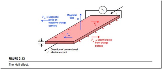
As shown in Figure 3.13, if an electric current flows through a conductor in a magnetic field, the magnetic field exerts a transverse force on the moving charge carriers, which tends to push them to one side of the conductor. This is most evident in a thin, flat conductor as illustrated. A build-up of charge at the sides of the conductors will balance this magnetic influence, producing a measurable voltage between the two sides of the conductor. The presence of this measurable transverse voltage is called the Hall effect, after E. H. Hall, who discovered it in 1879.
Note that the direction of the current I in the diagram is that of conventional current, so that the motion of electrons is in the opposite direction. This further confuses all the right-hand rule manipulations needed to obtain the direction of the forces.
As displayed in Figure 3.13, the Hall voltage VH is given by VH ¼ IB /(ned), where I is the induced electric current, B is the strength of the magnetic field, n is the density of mobile charges, e is the electron charge, and d is the thickness of the film.
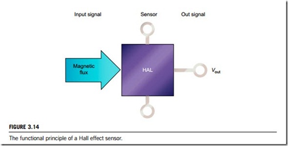
In the Hall effect sensor, the Hall effect element, with its entire evaluation circuitry, is integrated on a single silicon chip. The Hall effect plate with the current terminals and the taps for the Hall effect voltage are arranged on the surface of the crystal. This sensor element detects the components of the magnetic flux perpendicular to the surface of the chip, and emits a proportional electrical signal which is processed in the evaluation circuits which are integrated on the sensor chip. The functional principle of a Hall effect sensor is, as shown in Figure 3.14, that the output voltage of the sensor and the switching state, respectively, depend on the magnetic flux density through the Hall effect plate.
(2) Magnetoresistive sensors and switches
Magnetoresistance is the ability of some conductive materials to gain or lose some of their electrical resistance when placed inside a magnetic field. The resistivity of some such materials is greatly affected when the material is subjected to a magnetic field. The magnitude of this effect is known as magnetoresistance and can be expressed by the equation:
MR ¼ ðrðHÞ- rð0ÞÞ=rð0Þ:
where MR is the magnetoresistance, r(0) is the resistivity at zero magnetic fields, and r(H) is the resistivity in an applied magnetic field.
The magnetoresistance of conventional materials is quite small, but some materials with large magnetoresistance have now been synthesized. Depending on the magnitude of the effect produced, it is called either giant magnetoresistance (GMR) or colossal magnetoresistance (CMR).
Magnetoresistive sensor or switch elements are magnetically controllable resistors. The effect
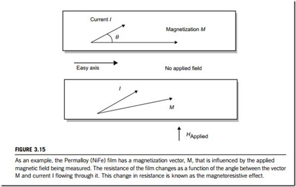
whereby the resistance of a thin, anisotropic, ferromagnetic layer changes through a magnetic field is utilized in these elements. The determining factor for the specific resistance is the angle formed by the internal direction of magnetization (M) and the direction of the current flow (I). Resistance is largest if the current flow (I) and the direction of magnetization run parallel. The resistance in the base material is smallest at an angle of 90o between the current flow (I) and the direction of magnetization (M).
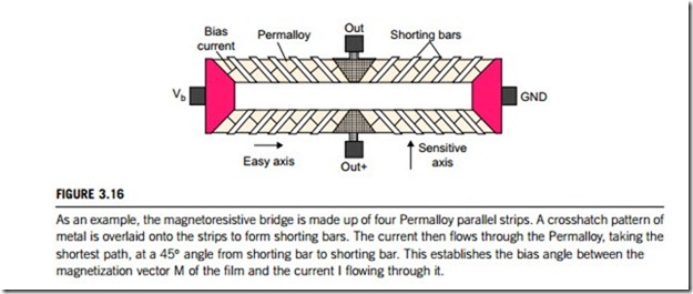
Highly conductive material is then joined to it at an angle of less than, 45o. The current passing the sensor element takes the shortest distance between these two ranges. This means that it flows at
a preferred direction of 45o against the longitudinal axis of the sensor element. Without an external field, the resistance of the element is then in the middle of its range. An external magnetic field with field strength (H) influences the internal direction of magnetization, which causes the resistance to change in proportion to its influence. Figure 3.15 gives an example using a Perm alloy (NiFe) film to illustrate that the resistance of a material depends upon the angle between the internal direction of magnetization M and the direction of the current flow (I).
The actual sensor element is often designed with four magnetic field sensitive resistors, that are interconnected to form a measuring bridge (Figure 3.16). The measuring bridge is energized and supplies a bridge voltage. A magnetic field, which influences the bridge branches by different degrees results in a voltage difference between the bridge branches which is then amplified and evaluated.
The sensor detects the movement of ferromagnetic structures (e.g., in gearwheels) caused by the changes in the magnetic flow. The sensor element is biased with a permanent magnet. A tooth or a gap moving past the sensor influences the magnetic field by different amounts. This causes changes in the magnetic field which depend on resistance values in a magnetoresistive sensor. The changes in the magnetic field can therefore be converted into an electric variable, and can also be conditioned accordingly. The output signal from the sensor is a square-wave voltage which reflects the changes in the magnetic field.
The voltage changes that result from the magnetic field changes are amplified and supplied to a Schmitt trigger after conditioning. If the effective signal reaches an adequate level, the output stage is set accordingly.
The sensor is used for noncontact rotational speed detection on ferromagnetic sensing objects such as gearwheels. The distance between the sensed object and the surface of the active sensor is described
as an air gap. The maximum possible air gap is dependent on the geometry of the object. The measurement principle dictates direction-dependent installation. The magnetoresistive sensor is sensitive to changes in the external magnetic field. For this reason the sensed objects should not have different degrees of magnetization.
(3) Magnetic switches
Most magnetic switches work by using one of two mechanisms; magnetic reed switches and magnetic level switches.
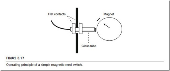
Magnetic reed switches normally consist of two overlapping flat contacts, which are sealed into a glass tube that is filled with inert gas. When approached by a permanent magnet, the contact ends attract each other and make contact. When the magnet is removed, the contacts separate immediately (Figure 3.17).
Magnetic level switches use the time-proven principle of repelling magnetic forces. One permanent magnet forms part of a float assembly which rises and falls with changing liquid level. A second permanent magnet is positioned within the switch head so that the adjacent poles of the two magnets repel each other through a nonmagnetic diaphragm. A change in liquid level moves the float through its permissible range of travel, causing the float magnet to pivot and repel the switch magnet. The resulting snap action of the repelling magnets actuates the switch.
Pneumatic actuators
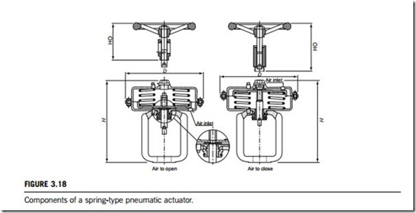
Pneumatics have had a variety of applications in control of industrial processes, from automotive and aircraft settings to modulate valves, to medical equipment such as dentistry drills to actuate torque movements. In contrast with other physical principles such as electrics or hydraulics, the operating torque of pneumatics makes possible a compact actuator that is economical to both install and operate. Pneumatic devices are also used where electric motors cannot be used for safety reasons, and where no water is supplied, such as in mining applications where rock drills are powered by air motors to preclude the need for electricity deep in the mine where explosive gases may be present. In many cases, it is easier to use a liquid or gas at high pressure rather than electricity to provide power for the actuator. Pneumatic actuators provide a very fast response but little power, whereas hydraulic systems can provide very great forces, but act more slowly. This is partly because gases are compressible and liquids are not. Pneumatic actuators (Figure 3.18) can offer the latest technology; a premium quality ball valve, a quality actuator designed to meet the torque requirements of the valve, and a mounting system which ensures alignment and rigidity.
Industrial pneumatics may be contrasted with hydraulics, which uses uncompressible liquids such as oil, or water combined with soluble oil, instead of air. Air is compressible, and therefore it is considered to be a fluid. Pneumatic principles dictate that the pressure formed in compressible liquids can be harnessed to give a high potential of power. Harnessing this potential has lead to the devel- opment of a number of pneumatic-powered operations in new areas. Both pneumatics and hydraulics are applications of fluid power.
Both linear and rotary pneumatic actuators use pressurized air to drive or rotate mechanical components. The flow of pressurized air produces the shift or rotation of moving components via a stem and spring, rack and pinion, cams, direct air or fluid pressure on a chamber or rotary vanes, or other mechanical linkage. A valve actuator is a device mounted on a valve that, in response to a signal, automatically moves the valve to the desired position using an outside power source. Pneumatic valve actuators convert air pressure into motion.
(1) Linear pneumatic actuators
A linear pneumatic actuator operates a combination of force created by air and by the force of a spring. The actuator shifts the positions of a control valve, by transmitting its motion through the stem. A rubber diaphragm separates the actuator housing into two air chambers. The left or upper chamber receives a supply of air through an opening in the top of the housing. The right or bottom chamber contains a spring that forces the diaphragm against mechanical stops in the upper chamber. Finally, a local indicator is connected to the stem to indicate the position of the valve.
The position of the valve is controlled by varying supplied air pressure in the left or upper chamber, which results in a varying force acting on the top of the diaphragm. Initially, without supply air, the spring forces the diaphragm upward against the mechanical stops and holds the valve fully open. As supply air pressure is increased from zero, its force on top of the diaphragm begins to overcome the opposing force of the spring. The causes the diaphragm to move rightward or downward, and the control valve to close. With increasing supply air pressure, the diaphragm will continue to move rightward or downward and compress the spring until the control valve is fully closed. Conversely, if supply air pressure is decreased, the spring will force the diaphragm leftward or upward and open the control valve. Additionally, if supply pressure is held constant at some value between zero and maximum, the valve will position at an intermediate point.
The valve can hence be positioned anywhere between fully open and fully closed in response to changes in the pressur of supplied air. A positioner is a device that regulates the supply air pressure to a pneumatic actuator. It does this by comparing the position demanded by the actuator with the control position of the valve. The requested position is transmitted by a pneumatic or electrical control signal from a controller to the positioner. The controller generates an output signal that represents the requested position. This signal is sent to the positioner. Externally, the positioner consists of an input connection for the control signal, a supply air input connection, a supply air output connection, a supply air vent connection, and a feedback linkage. Internally, it contains an intricate network of electrical transducers, air lines, valves, linkages, and necessary adjustments.
Other positioners may also provide controls for local valve positioning and gauges to indicate supply air pressure and controller pressure.
(2) Rotary pneumatic actuators
Pneumatic rotary actuators may have fixed or adjustable angular strokes, and can include such features as mechanical cushioning, closed-loop hydraulic dampening (by oil), and magnetic features for reading by a switch.
When the compressed air enters the actuator from the first tube nozzle, the air will push the double pistons toward both ends (cylinder end) for straight line movement. The gear on the piston causes the gear on the rotary shaft to rotate counterclockwise, and then the valve can open. This time, the air at both ends of the pneumatic actuator will drain through another tube nozzle.
Conversely, when the compressed air enters the actuator from the second tube nozzle, the gas will push the double pistons toward the middle for straight line movement. The rack on the piston drives the gear on the rotary shaft to rotate clockwise and then the valve can be closed. This time, the air at the middle of the pneumatic actuator will drain through the first tube nozzle. This is the standard driving principle. if required, a pneumatic actuator can be assembled into a driving principle that diffels from the standard type, which means opening the valve while rotating the rotary shaft clockwise and closing the valve while rotating the rotary shaft counterclockwise.
Hydraulic actuators
Pneumatic actuators are normally used to control processes that require a quick and accurate response, as they do not require a large amount of motive force. However, when a large amount of force is required to operate a valve, such as for main steam system valves, hydraulic actuators are normally used. A hydraulic actuator receives pressure energy and converts it to mechanical force and motion. Fluid power systems are manufactured by many organizations for a very wide range of applications, which often embody differing arrangements of components to provide the control functions required for the operation of diverse systems.
Table 3.4 gives the basic types of hydraulic actuators in three columns, (cylinder, valve, and motor), and the valve controlling source in three rows, (electro, servo, and piezoelectric). The motion type for each type of hydraulic actuator device is specified in each cell of the table, which indicates that
cylinders only have linear motion, valves can have both linear and rotary motions, and motors rotary motion only.
An actuator can be linear or rotary. A linear actuator gives force and motion outputs in a straight line. It is more commonly called a cylinder but is also referred to as a ram, reciprocating motor, or linear motor. A rotary actuator produces torque and rotating motion. It is more commonly called a hydraulic motor.
(1) Hydraulic cylinders and linear actuators
Hydraulic cylinders are actuation devices that use pressurized hydraulic fluid to produce linear motion and force. They are used in a variety of power transfer applications, and can be single or double action. A single action hydraulic cylinder is pressurized for motion in only one direction, whereas a double action hydraulic cylinder can move along the horizontal (x-axis) plane, the vertical (y-axis) plane, or along any other plane of motion.
Important operating specifications for hydraulic cylinders include the cylinder type, stroke, maximum operating pressure, bore diameter, and rod diameter. Stroke is the distance that the piston travels through the cylinder. Hydraulic cylinders can have a variety of stroke lengths, from fractions of an inch to many feet. The maximum operating pressure is the maximum working pressure the cylinder can sustain. The bore diameter refers to the diameter at the cylinder bore. The rod diameter refers to the diameter of the rod or piston used in the cylinder.
Choices for cylinder type include tie-rod, welded, and ram. A tie-rod cylinder is a hydraulic cylinder that uses one or more tie-rods to provide additional stability. Tie-rods are typically installed on the outside diameter of the cylinder housing. In many applications, the cylinder tie-rod bears the majority of the applied load. A welded cylinder is a smooth hydraulic cylinder that uses a heavy-duty welded cylinder housing to provide stability. A ram cylinder is a type of hydraulic cylinder that acts as a ram. A hydraulic ram is a device in which the cross-sectional area of the piston rod is more than one- half of the cross-sectional area of the moving components. Hydraulic rams are primarily used to push rather than pull, and are most commonly used in high-pressure applications.
(2) Hydraulic valves
Hydraulic valve actuators convert a fluid pressure supply into a motion. A valve actuator is a hydraulic actuator mounted on a valve that, in response to a signal, automatically moves the valve to the desired position using an outside power source. The actuators in hydraulic valves can be either linear, like cylinders, or rotary, like motors. The hydraulic actuator operates under servo-valve control; this provides regulated hydraulic fluid flow in a closed-loop system that has upper and lower cushions to protect the actuator from the effects of high-speed and high-mass loads. Piston movement is monitored via a linear voltage displacement transducer (LVDT), which provides an output voltage proportional to the displacement of the movable core extension to the actuator.
The outside power sources used by hydraulic valves are normally electronic, servo, piezoelectric.
(3) Hydraulic motors and rotary actuators
Hydraulic motors are powered by pressurized hydraulic fluid and transfer rotational kinetic energy to mechanical devices. Hydraulic motors, when powered by a mechanical source, can rotate in the reverse direction, and act as a pump.
Hydraulic rotary actuators use pressurized fluid to rotate mechanical components. The flow of fluid produces the rotation of moving components via a rack and pinion, cams, direct fluid pressure on rotary vanes, or other mechanical linkage. Hydraulic rotary actuators and pneumatic rotary actuators may have fixed or adjustable angular strokes, and can include such features as mechanical cushioning, closed-loop hydraulic dampening (oil), and magnetic features for reading by a switch.
Motor type is the most important consideration when looking for hydraulic motors. The choices include axial piston, radial piston, internal gear, external gear, and vane. An axial piston motor uses an axially mounted piston to generate mechanical energy. High-pressure flow into the motor forces the piston to move in the chamber, generating output torque. A radial-piston hydraulic motor uses pistons mounted radially about a central axis to generate energy. An alternate-form radial-piston motor uses multiple interconnected pistons, usually in a star pattern, to generate energy. Oil supply enters the piston chambers, moving each individual piston and generating torque. Multiple pistons increase the displacement per revolution through the motor, increasing the output torque. An internal gear motor uses internal gears to produce mechanical energy. Pressurized fluid turns the internal gears, producing output torque. An external gear motor uses externally mounted gears to produce mechanical energy. Pressurized fluid forces the external gears to turn, producing output torque. A vane motor uses a vane to generate mechanical energy. Pressurized fluid strikes the blades in the vane, causing it to rotate and produce output torque.
Additional operating specifications to consider include operating torque, pressure, speed, temperature, power, maximum fluid flow, maximum fluid viscosity, displacement per revolution, and motor weight. The operating torque is the torque that the motor is capable of delivering, which depends directly on the pressure of the working fluid delivered to the motor. The operating pressure is the pressure of the working fluid delivered to the hydraulic motor. The fluid is pressurized by an outside source before it is delivered to the motor. Working pressure affects operating torque, speed, flow, and horsepower of the motor. The operating speed is the speed at which the hydraulic motors’ moving parts rotate. Operating speed is expressed in terms of revolutions per minute or similar. The operating temperature is the fluid temperature range that the motor can accommodate. Minimum and maximum operating temperatures are dependent on the internal component materials of the motor, and can vary greatly between products. The power the motor is capable of delivering is dependent on the pressure and flow of the fluid through the motor. The maximum volumetric flow through the motor is expressed in terms of gallons per minute, or similar units. The maximum fluid viscosity the motor can accom- modate is a measure of the fluid’s resistance to shear, and is measured in centipoise (cP), a common metric unit of dynamic viscosity equal to 0.01 poise or 1 mP. The dynamic viscosity of water at 20oC is about 1 cP (the correct unit is cP, but cPs and cPo are sometimes used). The fluid volume displaced per revolution of the motor is measured in cubic centimetres (cc) per revolution, or similar units. The weight of the motor is measured in pounds or similar units.
3.4.5 Piezoelectric actuators
Piezoelectric actuators represent an important new group of actuators for active control of mechanical systems. Although the magnitudes of piezoelectric voltages, movements, or forces are small, and often require amplification (e.g., a typical disk of piezoelectric ceramic will increase or decrease in thickness by only a small fraction of a millimetre), piezoelectric materials have been adapted to an impressive range of applications that require only small amounts of displacement (typically less than a few thousandths of an inch). Today, piezoelectric ceramics are used in sensing applications, such as accelerometers, sensors, flow meters, level detectors, and hydrophones as well as in force or displacement sensors. The inverse piezoelectric effect is used in actuation applications, such as in motors and devices that precisely control position, and in generating sonic and ultrasonic signals.
Piezoelectric actuators can be used for the conversion of electrical energy to mechanical move- ment, for accurate positioning down to nanometer levels, for producing ultrasonic energy and sonar signals, and for the conversion of pressure and vibration into electrical energy. Piezoelectric actuators can also be manufactured in a variety of configurations and by a range of fabrication techniques. The industry recognizes these devices as monomorphs, bimorphs, stacks, co-fired actuators, and flexure elements. Piezoelectric actuators are found in telephones, stereo music systems, and musical instru- ments such as guitars and drums.
Piezoelectric actuators are beginning to appear in endoscope lenses used in medical treatment, and they are also used for valves in drilling equipment in offshore oil fields. They are also used to control hydraulic valves, act as small-volume pumps or special-purpose motors, and in other applications. Piezoelectric actuators that combine a number of superior characteristics will doubtless continue to evolve into powerful devices that support our society in the future.
(1) Operating principle
In 1880, Jacques and Pierre Curie discovered an unusual characteristic of certain crystalline minerals; when subjected to a mechanical force, the crystals became electrically polarized. Tension and compression generated voltages of opposite polarity, and in proportion to the applied force. Subse- quently, the converse of this relationship was confirmed; if one of these voltage-generating crystals was exposed to an electric field it lengthened or shortened according to the polarity of the field, and in proportion to its strength. These behaviors were called the piezoelectric effect and the inverse piezoelectric effect, respectively.
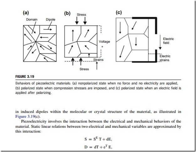
The findings by Jacques and Pierre Curie have been confirmed again and again since then. Many polymers, ceramics, and molecules such as water are permanently polarized; some parts of the molecule are positively charged, and others are negatively charged. This behavior of piezoelectric materials is depicted in Figure 3.19(a). When the material changes dimensions as a result of an imposed mechanical force, a permanently polarized material such as quartz (SiO2) or barium titanate (BaTiO3) will produce an electric field. This behavior of piezoelectric materials when subject to an imposed force is depicted in Figure 3.19(b). Furthermore, when an electric field is applied to these materials, the polarized molecules within them will align themselves with the electric field, resulting
where S is the strain tensor, T is the stress tensor, E is an electric field vector, D is the electric displacement vector, SE is the elastic compliance matrix when subjected to a constant electric field (the superscript E denotes that the electric field is constant), d is the matrix of piezoelectric constants, and eT is the permittivity measured at constant stress.
The piezoelectric effect is, however, very nonlinear in nature. Piezoelectric materials exhibit, for example, strong hysteresis and drift that is not included in the above model. It should be noted, too, that the dynamics of the material are not described by the two equations above.
(2) Basic types
Piezoelectric devices make use of direct and inverse piezoelectric effects to perform a function. Some materials both these effects. For example, ceramics acquire a charge when being compressed, twisted or distorted, and produced physical displacements when electric voltages are imposed, several types of devices are available, some of the most important of which are listed here.
(1) Piezoelectric actuators
Piezoelectric actuators are devices that produce a small displacement with a high force capability when voltage is applied. There are many applications where a piezoelectric actuator may be used, such as ultra-precise positioning and in the generation and handling of high forces or pressures in static or dynamic situations.
Actuator configuration can vary greatly, depending on application. Piezoelectric stack or multilayer actuators are manufactured by stacking up piezoelectric disks or plates, the axis of the stack being the axis of linear motion that occurs when a voltage is applied. Tube actuators are monolithic devices that contract laterally and longitudinally when a voltage is applied between the inner and outer electrodes. A disk actuator is a device in the shape of a planar disk. Ring actuators are disk actuators with a center bore, making the actuator axis accessible for optical, mechanical, or electrical purposes. Other less common configurations include block, disk, bender, and bimorph styles.
These devices can also be ultrasonic. Ultrasonic actuators are specifically designed to produce strokes of several micrometers at ultrasonic (>20 kHz) frequencies. They are especially useful for controlling vibration, positioning applications, and quick switching. In addition, piezoelectric actua- tors can be either direct or amplified. The effect of amplification is not only larger displacement, but it can also result in slower response times.
The critical specifications for piezoelectric actuators are displacement, force, and operating voltage of the actuator. Other factors to consider are stiffness, resonant frequency, and capacitance. Stiffness is a term used to describe the force needed to achieve a certain deformation of a structure. For piezoelectric actuators, it is the force needed to elongate the device by a certain amount, nor- mally specified in terms of Newtons per micrometer. Resonance is the frequency at which the actuators respond with maximum output amplitude. The capacitance is a function of the excitation voltage frequency.
(2) Piezoelectric motors
Piezoelectric motors use a piezoelectric, ceramic element to produce ultrasonic vibrations of an appropriate type in a stator structure. The elliptical movements of the stator are converted into the movement of a slider which is pressed into frictional contact with the stator. The consequent move- ment may either be rotational or linear depending on the design of the structure. Linear piezoelectric motors typically offer one degree of freedom, such as in linear stages, but they can be combined to provide more complex positioning factors. Rotating piezoelectric motors are commonly used in submicrometer positioning devices. Large mechanical torque can be achieved by combining several of these rotational units.
Piezoelectric motors have a number of potential advantages over conventional electromagnetic motors. They are generally small and compact for their power output, and provide greater force and torque than their dimensions would seem to indicate. In addition to a very positive size to power ratio, piezoelectric motors have high holding torque maintained at zero input power, and they offer low inertia from their rotors, providing rapid start and stop characteristics. Addi- tionally, they are unaffected by electromagnetic fields, which can hamper other motor types. Piezoelectric motors usually do not produce magnetic fields and also are not affected by external magnetic fields. Because they operate at ultrasonic frequencies, these motors do not produce sound during operation.
(3) Multilayer piezoelectric benders
High efficiency, low-voltage, multilayer benders have been developed to meet the growing demand for precise, controllable, and repeatable deflection devices in the millimetre and micrometer range. Multilayer, piezoelectric, ceramic benders are devices capable of rapid (< 10 ms) millimetre move- ments with micrometer precision. They utilize the inverse piezoelectric effect, in which an electric field creates a cantilever bending effect. By making the ceramic layers very thin, between 20 and 40 mm, deflections can be generated with low power consumption at operating voltages from -10 to þ60 V. With an electrical field of <3 kV/mm, large deflections per unit volume can be achieved with
high reliability.
(4) Piezoelectric drivers and piezoelectric amplifiers
Piezoelectric drivers and piezoelectric amplifiers have been developed to match the requirements for driving and controlling piezoelectric actuators and stages in some applications. Standard linear amplifier products are simple voltage followers that amplify a low-voltage input signal, and others are recommended for use as integrated or stand-alone systems in applications requireing more advanced capabilities for closed-loop servo control. A voltage amplifier is typically needed to control piezoelectric actuators due to the high operating voltage needed for the former. In other words, before the computer, through a direct to alternating converter, provides the control signal, it must be amplified.
Piezoelectric actuators theoretically have an unlimited resolution. Therefore, every infinitely small voltage step caused for example, by the noise of the amplifier, is transformed into an infinitely small mechanical shift. The noise characteristics of the amplifier are very important in design of a precision positioning system.
