Electric motors are required to be protected against overload, NEC Section 430 32. Overload protection is usually provided as a device responsive to motor current or as a thermal protector integral with the motor. A device responsive to motor current could be a fuse, a circuit breaker, an overload heater, or a thermal reset switch in the motor housing. An automatically resetting thermal switch placed in the windings will sense winding temperature directly.
The service factor or temperature rise must be known from the motor nameplate when selecting the proper size motor overload protection. These are indicators of the amount of overload a motor can withstand. If a motor has a service factor of 1 . 15 or greater, the manufacturer has designed extra overload capacity into the motor. In this case, the overload protection may be sized as large as 125% of the nameplate full load current. Internal heat is damaging to motor winding insulation. A motor with a temperature rise of 40°C (104oF) or less has been designed to run relatively cool; therefore, it has greater overload capacity. The overload protection may be sized as large as 125% of the nameplate full load current. A service factor of less than 1. 15 or a temperature rise of more than 40°C (104°F) indicates little overload capacity. The overload protection under these circumstances is sized not larger than 115% of the nameplate full load current
Size the motor overload protective device at not more than these percents of nameplate full load current:
• Service factor 1 .15 or greater, 125%
• Temperature rise not greater than 40°C (1 04oF), 125%
• Service factor smaller than 1. 15, 115%
• Temperature rise greater than 40°C (104°F), 115%
A time delay fuse may serve as motor overload protection. Plug fuses or cartridge fuses are used for small motors. The fuse size is determined by selecting the proper multiplying factor, 1.15 or 1.25, based upon the service factor and temperature rise. Standard fuse sizes smaller than 30 A are listed in Unit 6
Problem 17-4
A 3/4 hp, single phase water pump motor is operatec at 230 V and full load current of 6. 9 A. The motor has’ service factor of 1.15 and a code letter K. Determine the maximum size time delay fuses permitted to serve a~ running overload protection.
Solution
The full load current from NEC Table 430 148 1: 6.9 A. With a service factor of 1.15, the overload pro tective device may be 1.25 times the full load current
1.25 X 6.9 A= 8.6 A
Choose an 8 A fuse (refer to fuse sizes listed in Unit 6). If an 8 A fuse will not work, then the next larger size. 9 A, may be used provided it does not exceed 140% oJ the motor nameplate current, 1.4 X 6. 9 A 9. 7 A NEC Section 430 34.
Circuit breakers could be used as running overloac protection, but they are not available in small ampen sizes. If they are used for large motors, they will usuall) trip on starting if they are sized small enough to provid’ overload protection
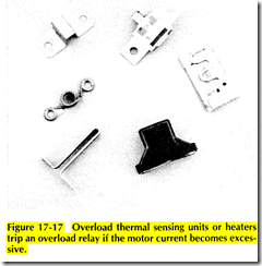
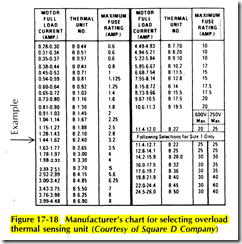
Magnetic and manual motor starters have an over load relay or trip mechanism which is activated by ; heater sensitive to the motor current. Typical motor over load heaters are shown in Figure 17 17. The manufac turer of the motor starter provides a chart inside th’ motor starter listing the part number for thermal overload heaters. The heaters are sized according to the actual full load current listed on the motor nameplate. Find the heater number from the manufacturer’s list corresponding to the motor nameplate full load current. A typical manufacturer’s overload heat selection chart is shown in Figure 17 18
An example will help to learn how the overload
heater chart is used. A 3 phase motor nameplate fullload current for 230 V operation is 1. 5 A. The proper overload heater to use is thermal unit No. B 2.40. The NEC allows this heater to be sized at 125% of the motor nameplate full load current provided the service factor is 1. 15 or larger, or the temperature rise is not greater than 40°C (104°F). The manufacturer has taken this into consideration when setting up the chart. If the service factor is less than 1.15 or if the temperature rise is greater than 40°C ( 104°F), then the heater will be 10% oversized. The motor is then vulnerable to burnout. If the motor service factor is less than 1.15, multiply the motor fullload current on the nameplate by 0. 9 and use this new value to size the overload heater. For the example, multiplying 1.5 A by 0.9 gives 1.35 A. The overload heater corresponding to 1.35 A is a thermal unit No. B 2.1 0
A thermal protector integral with the motor and installed by the manufacturer is permitted to serve as the overload protection, NEC Section 430 32(a)(2). The manufacturer is required to size the thermal protector according to the multiplying factors in the NEC
The number of overload protective devices required for a motor is specified in the NEC. If fuses are used, one fuse shall be placed in each ungrounded conductor supplying the motor, NEC Section 430 36. The number of thermal overload heaters is specified in NEC Table 430 37. The minimum is one for a single phase motor, and three for a 3 phase motor
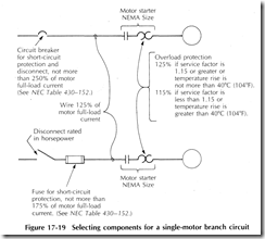
The rules for sizing components for a single motor branch circuit are summarized in Figure 17 19
Problem 17-5
A single phase, 3 hp electric motor operates at 230 V, and draws 17 A full load current. The service factor is 1. 2 and the code letter is M. The motor disconnect is a fusible switch and the controller is a magnetic motor starter. Determine the following:
1 . Minimum rating disconnect switch
2. Minimum NEMA size motor starter
3. Minimum size copper THW wire
4. Time-delay fuse size for short-circuit and groundfault protection
5. Proper overload heater from the chart in Figure 17-18
Solution
1. The disconnect switch must be rated in horsepower; therefore, the minimum is 3 hp
2. Using Table 17 1 , the minimum size motor starter for a single phase, 3 hp motor is NEMA Size 1
3. Look up the motor full load current in NEC Table 430 148. Multiply the current by 1.25.
1. 25 X 17 A = 21 A
From NEC Table 310 16 (refer to Unit 9), the minimum copper THW wire size is No. 12 AWG.
4. The short circuit time delay fuse multiplier is found in NEC Table 430 152 for a single phase motor with the code letter M. Multiply the full load current by 1.75.
1 .7 5 X 17 A = 30 A
Use a 30-A time-delay fuse.
5. The overload heater is based upon l 25% of full load current because the service factor is greater than 1.15. Therefore, look up the heater part number corresponding to a motor full load current of 17 A. The proper thermal overload heater is thermal unit No. B 32~


