connecting Resistors in series
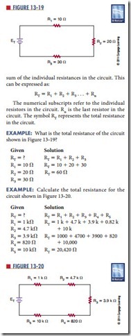
A series circuit contains two or more resistors and pro‑ vides one path for current to flow. The current flows from the negative side of the voltage source through each resistor to the positive side of the voltage source. If there is only one path for current to flow between two points in a circuit, the circuit is a series circuit.
The more resistors connected in series, the more opposition there is to current flow. The more opposition there is to current flow, the higher the resistance in the circuit. In other words, when a resistor is added in series to a circuit, the total resistance in the circuit increases. The total resistance in a series circuit is the
Related posts:
Lighting Circuits:The Incandescent Lamp
GENERATOR COMPONENTS, AUXILIARIES, AND EXCITATION:TURBINE-GENERATOR COMPONENTS AND THE STATOR
INTRODUCTION TO CONVENTIONAL D.C. MOTORS
Three-phase Distribution Boards And Socket Circuits:Three-phase Supplies
The SCR:The SCR in a DC Circuit
The Motor And Starting Methods
THE MMF OF ROTOR WINDINGS
POWER ELECTRONICS, RECTIFIERS, AND PULSE-WIDTH MODULATION INVERTERS:FILTERING RECTIFIER OUTPUT
The Turbine and How It Works
FIELD INTERFACES:FIELDBUSES
power Supplies:circuit-protection Devices
ELECTRONIC CONCEPTS AND MORE INTERESTING THAN YOU THINK:MAGNETISM
Capacitor Test Formula
Stepping Motors
