The impact that digital methods have made on audio has been at least as remarkable as it was on computing. Ian Sinclair uses this chapter to introduce the digital methods that seem so alien to anyone trained in analogue systems.
Introduction
The term digital audio is used so freely by so many that you could be excused for thinking there was nothing much new to tell. It is easy in fast conversation to present the impression of immense knowledge on the subject but it is more difficult to express the ideas concisely yet readably. The range of topics and disciplines that need to be harnessed in order to cover the field of digital audio is very wide and some of the concepts may appear paradoxical at first sight. One way of covering the topics would be to go for the apparent precision of the mathematical statement but, although this has its just place, a simpler physical
understanding of the principles is of greater importance here. Thus in writing this chapter we steer between excessive arithmetic precision and ambiguous oversimplified description.
Analogue and Digital
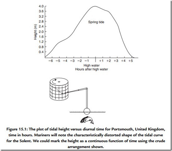
Many of the physical things that we can sense in our environment appear to us to be part of a continuous range of sensation. For example, throughout the day much of coastal England is subject to tides. The cycle of tidal height can be plotted throughout the day. Imagine a pen plotter marking the height on a drum in much the same way as a barograph is arranged (Figure 15.1). The continuous line that is plotted is a feature of analogue signals in which the information is carried as a continuous infinitely fine variation of a voltage, current, or, as in this case, height of the sea level.
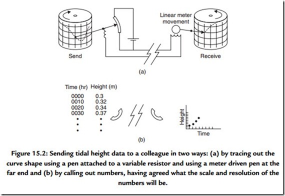
When we attempt to take a measurement from this plot we will need to recognize the effects of limited measurement accuracy and resolution. As we attempt greater resolution we will find that we approach a limit described by the noise or random errors in the measurement technique. You should appreciate the difference between resolution and accuracy since inaccuracy gives rise to distortion in the measurement due to some nonlinearity in the measurement process. This facility of measurement is useful. Suppose, for example, that we wished to send the information regarding the tidal heights we had measured to a colleague in another part of the country. One, admittedly crude, method might involve turning the drum as we traced out the plotted shape while at the far end an
electrically driven pen wrote the same shape onto a second drum [Figure 15.2(a)]. In this method we would be subject to the nonlinearity of both the reading pen and the writing pen at the far end. We would also have to come to terms with the noise that the line, and any amplifiers, between us would add to the signal describing the plot. This additive property of noise and distortion is characteristic of handling a signal in its analogue form and, if an analogue signal has to travel through many such links, then it can be appreciated that the quality of the analogue signal is abraded irretrievably.
As a contrast consider describing the shape of the curve to your colleague by measuring the height of the curve at frequent intervals around the drum [Figure 15.2(b)]. You’ll need to agree first that you will make the measurement at each 10-min mark on the drum, for example, and you will need to agree on the units of the measurement. Your colleague will now receive a string of numbers from you. The noise of the line and its associated amplifiers will not affect the accuracy of the received information since the received information should be a recognizable number. The distortion and noise performance of the line must be gross for the spoken numbers to be garbled and thus you are very well assured of correctly conveying the information requested. At the receiving end the numbers are plotted on to the chart and, in the simplest approach, they can be simply joined up with straight lines. The result will be a curve looking very much like the original.
Let’s look at this analogy a little more closely. We have already recognized that we have had to agree on the time interval between each measurement and on the meaning of the units we will use. The optimum choice for this rate is determined by the fastest rate at which the tidal height changes. If, within the 10-minute interval chosen, the tidal height could have ebbed and flowed then we would find that this nuance in the change of tidal height would not be reflected in our set of readings. At this stage we would need to recognize the need to decrease the interval between readings. We will have to agree on the resolution of the measurement, since, if an arbitrarily fine resolution is requested, it will take a much longer time for all of the information to be conveyed or transmitted. We will also need to recognize the effect of inaccuracies in marking off the time intervals at both the transmit or coding end and the receiving end since this is a source of error that affects each end independently.
In this simple example of digitizing a simple wave shape we have turned over a few ideas. We note that the method is robust and relatively immune to noise and distortion in the transmission and we note also that, provided we agree on what the time interval between readings should represent, small amounts of error in the timing of the reception of each piece of data will be completely removed when the data are plotted. We also note that greater resolution requires a longer time and that the choice of time interval affects our ability to resolve the shape of the curve. All of these concepts have their own special terms and we will meet them slightly more formally.
In the example just given we used implicitly the usual decimal base for counting. In the decimal base there are 10 digits (0 through 9). As we count beyond 9 we adopt the convention that we increment our count of the number of tens by one and recommence counting in the units column from 0. The process is repeated for the count of hundreds, thousands, and so on. Each column thus represents the number of powers of 10 (10 = 101, 100 = 102, 1000 = 103, and so on). We are not restricted to using the number base of 10 for counting. Among the bases in common use these days are base 16 (known more commonly as the hexadecimal base), base 8 (known as octal), and the simplest of them all, base 2 (known as binary). Some of these scales have been, and continue to be, in common use. We recognize that the old coinage system in the United Kingdom used the base of 12 for pennies, as, indeed, the old way of marking distance still uses the unit of 12 inches to a foot.
The binary counting scale has many useful properties. Counting in the base of 2 means that there can only be two unique digits, 1 and 0. Thus each column must represent a power of 2 (2 = 21, 4 = 22, 8 = 23, 16 = 24, and so on) and, by convention, we use a 1 to mark the presence of a power of 2 in a given column. We can represent any number by adding up an appropriate collection of powers of 2 and, if you try it, remember that 20 is equal to 1. We refer to each symbol as a bit (actually a contraction of the words binary digit). The bit that appears in the units column is referred to as the least significant bit ( LSB), and the bit position that carries the most weight is referred to as the most significant bit (MSB).
Binary arithmetic is relatively easy to perform since the result of any arithmetic operation on a single bit can only be either 1 or 0.
We have two small puzzles at this stage. The first concerns how we represent numbers that are smaller than unity and the second is how negative numbers are represented. In the everyday decimal (base of 10) system we have adopted the convention that numbers which appear to the right of the decimal point indicate successively smaller values. This is in exactly the opposite way in which numbers appearing to the left of the decimal point indicated the presence of increasing powers of 10. Thus successive columns represent 0.1 = 1/10 = 10-1, 0.01 = 1/100 = 10-2, 0.001 = 1/1000 = 10-3, and so on.
We follow the same idea for binary numbers and thus the successive columns represent 0.5 = 1/2 = 2-1, 0.25 = 1/4 = 2-2, 0.125 = 1/8 = 2-3, and so on.
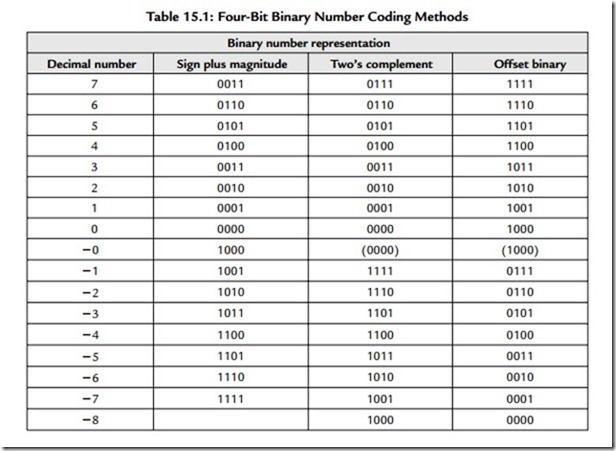
One of the most useful properties of binary numbers is the ease with which arithmetic operations can be carried out by simple binary logic. For this to be viable there has to be a way of including some sign in the number itself since we have only the two symbols 0 and 1. Here are two ways it can be done. We can add a 1 at the beginning of the number to indicate that it was negative or we can use a more flexible technique known as two’s complement. Here the positive numbers appear as we would expect but the negative numbering is formed by subtracting the value of the intended negative number from the largest possible positive number incremented by 1. Table 15.1 shows both of these approaches. The use of a sign bit is only possible because we will arrange that we will use the same numbering and marking convention. We will thus know the size of the largest
positive or negative number we can count to. The simple use of a sign bit leads to two values for zero, which is not elegant or useful. One of the advantages of two’s complement coding is that it makes subtraction simply a matter of addition. Arithmetic processes are at the heart of digital signal processing and thus hold the key to handling digitized audio signals.
There are many advantages to be gained by handling analogue signals in digitized form and, in no particular order, they include:
● great immunity from noise since the digitized signal can only be 1 or 0;
● exactly repeatable behavior;
● ability to correct for errors when they do occur;
● simple arithmetic operations, very easy for computers;
● more flexible processing possible and easy programmability;
● low cost potential; and
● processing can be independent of real time.


