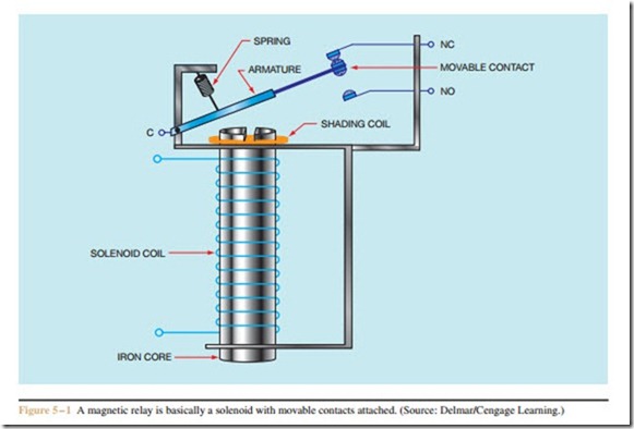
Relays and contactors are electromechanical switches. They operate on the solenoid principle. A coil of wire is connected to an electric current. The magnetic field developed by the current is concentrated in an iron pole piece. The electromagnet attracts a metal armature. Contacts are connected to the metal armature. When the coil is energized, the contacts will open or close. There are two basic methods of constructing a relay or contactor. The clapper type uses one movable contact to make connection with a stationary contact. The bridge type uses a movable contact to make connection between two stationary contacts.
Relays
Relays are electromechanical switches that contain auxiliary contacts. Auxiliary contacts are small and are intended to be used for control applications. As a general rule, they are not intended to control large amounts of current. Current ratings for most relays can vary from 1 to 10 amperes, depending on the manufacturer and type of relay. A clapper type relay is illustrated in Figure 5 – 1. When the coil is energized, the armature is attracted to the iron core inside the coil. This causes the movable contact to break away from one stationary
contact and make connection with another. The common terminal is connected to the armature, which is the movable part of the relay. The movable contact is attached to the armature. The two stationary contacts form the normally closed and normally open contacts. A spring returns the armature to the normally closed position when power is removed from the coil. The shading coil is necessary to prevent the contacts from chattering. All solenoids that operate on alternating current must have a shading coil. Relays that operate on direct current do not require them. A clapper type relay is shown in Figure 5 – 2.
Bridge Type Relay
A bridge type relay operates by drawing a piece of metal or plunger inside a coil (Figure 5 – 3). The plunger is connected to a bar that contains movable contacts. The movable contacts are mounted on springs and are insulated from the bar. The plunger and bar assembly are called the armature because they are the moving part of the relay. Bridge contacts receive their
name because when the solenoid coil is energized and the plunger is drawn inside the coil, the movable contacts bridge across the two stationary contacts. Bridge contacts can control more voltage than the clapper type because they break connection at two places instead of one. When power is removed from the coil, the force of gravity or a spring returns the movable contacts to their original position. A relay with bridge type contacts is shown in Figure 5 – 4.
