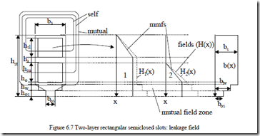
We consider the coils are chorded (Figure 6.7).
Let us consider that both layers contribute a field in the slot and add the effects. The total magnetic energy in the slot volume is used to calculate the leakage inductance Lsls.
Lsls = 2L2 e h∫stµ0 [H x1( )+ H2 ( )x ]2 dx ⋅b x( ) (6.22)
b sl
n Ibcls for hsl < x < hsl + hi
H x1( )+ H2( )x = n Ibcls + n Icoscu bs γk (x −hhslsu−hi ); (6.23)
for hsl + hi < x < hsl + hi + hsu
n Ibcli + n Icoscu bi γk ; for x > hsl + hi + hsu
with bi = b or bw os
The phase shift between currents in lower and upper layer coils of slot K is γK and ncl, ncu are the number of turns of the two coils. Adding up the effect of all slots per phase (1/3 of total number of slots), the average slot leakage inductance per phase Lsl is obtained.
While (6.23) is valid for general windings with different number of turn/coil and different phases in same slots, we may obtain simplified solutions for identical coils in slots ncl = ncu = nc.
![]() λsk = µ0 (2Lnslc )2 Le = 14 (hsl + h3subcoss 2 γk )+ hbsus + hsu cosbs γk + (6.24)
λsk = µ0 (2Lnslc )2 Le = 14 (hsl + h3subcoss 2 γk )+ hbsus + hsu cosbs γk + (6.24)
+ bhsi + (1+ cosγ)2 hbos + hbww + hbosos
Although (6.24) is quite general–for two-layer windings with equal coils in slots–the eventual different number of turns per coil can be lumped into cosγ as Kcosγ with K = ncu/ncl. In this latter case the factor 4 will be replaced by (1 + K)2.
In integer and fractionary slot windings with random coil throws, (6.24) should prove expeditious. All phase slots contributions are added up.
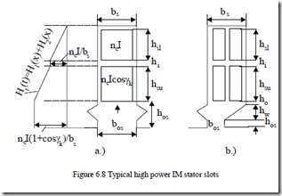
Other realistic rectangular slot shapes for large power IMs (Figure 6.8) may also be handled via (6.24) with minor adaptations.
For full pitch coils (cosγK = 1.0) symmetric winding (hsu = hsl = hs′) (6.24) becomes
(λsk )hγ =ksu =0hsl =hs ‘ = 23h ‘bss + 4hbis + hb0s + hbww + hbosos (6.25)
Further on with hi = ho = hw = 0 and 2hs′ = hs, we reobtain (6.19), as expected.
. ROUNDED SHAPE SLOT LEAKAGE INDUCTANCE/TWO LAYERS
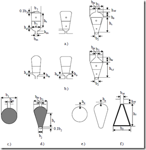
Although the integral in (6.2) does not have exact analytical solutions for slots with rounded corners, or purely circular slots (Figure 6.9), so typical to low-power IMs, some approximate solutions have become standard for design purposes:
• For slots a.) in Figure 6.9,
λs,r ≈ 3(b1s,r+ b12 ) + bos,ros,r + hb1o − 2os,rb1 + 0.785K2 (6.26)
2h K h
K ; for 1≤ βy ≤ 2
• For slots b.), 2h
λs,r ≈ 3(b1s,r+Kb1 ) + hbos,ros,r + hb1o + b1 +3h2wbos,r K2 (6.28)
For slots c.), λ =r 0.785− 2bbor1 + hboror ≈ 0.66 + hboror (6.29)
For slots d.), 2 λ r = 3hbr1 1− π8bA1b2 + 0.66 − 2hbor1 + hb oror
(6.30)
where Ab is the bar cross section.
If the slots in Figure 6.9c, d are closed (ho = 0) (Figure 6.9e) the terms hor/bor in Equations (6.29, 6.30) may be replaced by a term dependent on the bar current which saturates the iron bridge.
This is only an empirical approximation for saturation effects in closed rotor slots, potentially useful for very preliminary design purposes.
For the trapezoidal slot (Figure 6.9f), typical for deep rotor bars in high power IMs, by conformal transformations, the slot permeance is, approximately
[3]
b2 2
λ =r π1 ln b4or b2 −1 + bbor2b22 +1⋅ln bbbor22 +−11 + hboror (6.32)
bor bor bor
The term in square brackets may be used to calculate the geometrical permeance of any trapezoidal slot section (wedge section, for example).
Finally for stator (and rotors) with radial ventilation ducts (channels) additional slot leakage terms have to be added. [8]
For more complicated rotor cage slots used in high skin effect (low starting current, high starting torque) applications, where the skin effect is to be considered, pure analytical solutions are hardly feasible, although many are still in industrial use. Realistic computer-aided methods are given in Chapter 8.


