Voltage Regulator Systems
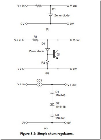
Electronic voltage regulator systems can operate in two distinct modes, each with their own advantages and drawbacks: shunt and series. The shunt systems operate by drawing current from the supply at a level that is calculated to be somewhat greater than maximum value, which will be consumed by the load. A typical shunt regulator circuit is shown in Figure 5.2(a), in which the regulator device is an avalanche or Zener diode or a two- terminal band-gap element for low current, high stability requirements. Such simple circuits are normally only used for relatively low current applications, although high power avalanche diodes are available. If high power shunt regulators are needed, a better
approach is to use a combination of avalanche diode and power transistor, as shown in Figure 5.2(b). The obvious snag is that in order for such a system to work, there must be a continuous current drain that is rather larger than the maximum likely to be drawn by the load, which is wasteful. The main advantages of the shunt regulator system are that it is simple and that it can be used even when the available supply voltage is only a little greater than the required output voltage. Avalanche and Zener diodes are noisy, electrically speaking, although their noise can be lessened by connecting a low ESR capacitor in parallel with them. For applications where only a low voltage is needed and its actual value is not very important but a low circuit noise is essential, a simple arrangement is to use a string of silicon diodes, as shown in Figure 5.2(c). Each of these diodes will have a forward direction voltage drop of about 0.6 V, depending on the current flowing though them. Light-emitting diodes have also been recommended in this application, for which a typical forward voltage drop would be about 2.4 V, depending on the LED type and its forward current. All of these simple shunt regulator circuits will perform better if the input resistor (R1) is replaced by a constant current source, shown as CC1.
