The primary function of the power supply is to convert alternating current (AC) to direct current (DC). The power supply may increase or decrease the incoming AC voltage by means of a transformer.
Once the voltage is at the desired level, it is converted to a DC voltage through a process called rectification. The rectified voltage still contains an AC signal, referred to as a ripple frequency. The ripple frequency is removed with a filter.
To ensure that the output voltage remains at a constant level, a voltage regulator is used. The voltage regulator holds the output voltage at a constant level.
Transformers
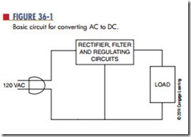
The circuit shown in Figure 36-1 represents a basic cir- cuit that converts AC to DC. It converts the sine wave from the AC power source to direct current, without a transformer. One disadvantage with this type of circuit occurs when the load requires a higher or lower voltage.
Another disadvantage of this basic circuit is that one side of the AC power source is connected to the rectifier circuit and the other side is connected directly to the chassis of the device. This can present a serious shock hazard when the chassis is not isolated from the user.
When a device uses a two-prong plug, it provides two ways of plugging the device to the AC power source. One way could connect the chassis directly to the hot side of the AC source. If the user touches ground and the chassis, it could result in a lethal shock.
When using test equipment with two-prong plugs, if one piece is plugged in with a reversed connection, a voltage could exist between two pieces of test
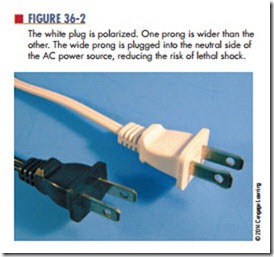
equipment that could be lethal. Figure 36-2 shows two 2-prong plugs. In one, the prongs are the same width; the other shows that one prong is wider than the other and is referred to as a polarized plug. The polarized plug eliminates the chance of plugging in a device and making the chassis hot. The wide prong is plugged into the neutral side of the AC power source.
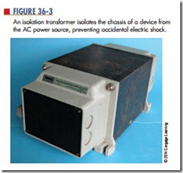
Devices that are built without transformers tend to be inexpensive consumer products. These devices use plastic cabinets, knobs, and switches to eliminate potential shock hazards. When servicing these devices without transformers, an isolation transformer must be used (Figure 36-3). The isolation transformer
isolates the chassis from the AC power source, pre- venting accidental electric shock.
Transformers are therefore used in power supplies to isolate the power supply from the AC voltage source. They are also used to step up voltages if higher voltages are required or to step down voltages if lower voltages are required. If transformers are used in power supplies, the AC power source is connected only to the primary of the transformer. This isolates the electrical circuits from the power source. When selecting a transformer, its primary power rating is the first concern. The most common primary ratings are 110 to 120 volts and 220 to 240 volts. The next concern is the transformer’s frequency. Some frequencies are 50 to 60 hertz, 400 hertz, and 10,000 hertz. The third concern is the secondary voltage and current ratings of the transformer. The final concern is its power-handling capability, or volt-ampere rating, which is essentially the amount of power that can be delivered to the secondary of the transformer. It is given as volt-amperes because of the loads that can be placed on the secondary.
Questions
1. Why are transformers used in power supplies?
2. How is a transformer connected in a power supply?
3. What safety consideration is given to transformers used in a power supply?
4. What are the important considerations when selecting a transformer for a power supply?
How are transformers rated?


