DESIGN CRITERIA
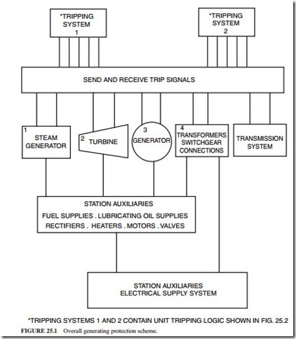
The protective systems are designed to disconnect the faulty system when faults occur. The following are the main design requirements for the protective systems in power stations:
1. A system must be disconnected as quickly as possible when a fault occurs on it.
2. A secondary or a backup protection must be able to clear the fault if the main system protection did not clear it.
3. The system protection must be designed to match as closely as possible its operating characteristics; e.g., the generator negative sequence protection must be designed to match its thermal withstand to negative phase sequence currents.
The protection systems should generally be designed to prevent failure of a single protective device from causing a trip or allowing a fault to remain connected to the system. The exception occurs where the probability of failure of the protective device is very low such that the event is not considered credible, i.e., electromagnetic relays having a very low failure rate. These relays are used in electrical protection systems. They are normally installed in a fully dust-proofed environment where the temperature and humidity are controlled. All other protection systems using plant-mounted tripping devices rely on a “two out of three” logic to initiate a trip.
The protective relay output contacts must be allocated such that the operation of any relay will not trip more than one protective system. This is done to facilitate diagnostic testing while the unit is operating and one protective system is isolated. The trips which would remain active following a unit shutdown should be removed, e.g., the mechanical trips of the turbine and generator.
The equipment of a tripping system should be physically segregated from the other trip- ping systems as much as possible. This can be done by using separate relay panels and terminal blocks. The routing of the tripping system cables should also be different. The electrical connections for the protective relay circuits should be in accordance with the appro- priate standards and codes.
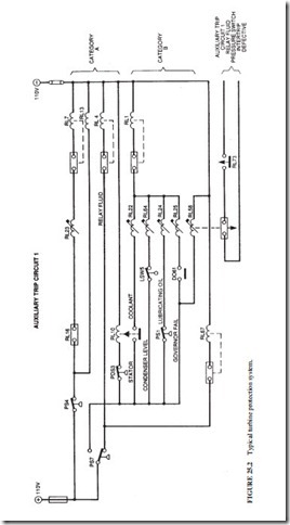
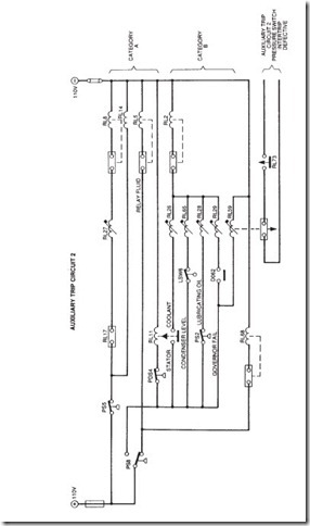
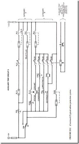
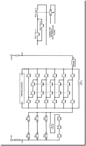
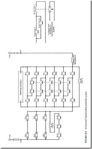
Figure 25.2 illustrates a typical turbine protection system in a power station. There is a protection circuit for each of the main plant systems. A trip relay trips the unit when any of the protection devices shown operates. All fault conditions initiate the same signal to trip the unit. Category A faults are those requiring immediate disconnection of the unit from the grid when the fault occurs. Category B faults are those requiring the circuit breaker connecting the unit to the grid to remain closed following the fault to prevent rotor overspeed. The circuit breaker will eventually open on reverse power or low forward power.
