DC TRIPPING SYSTEMS
Logic Diagram
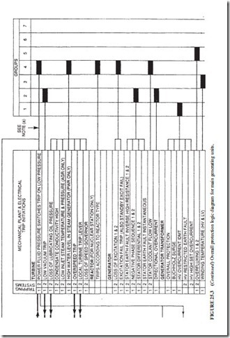
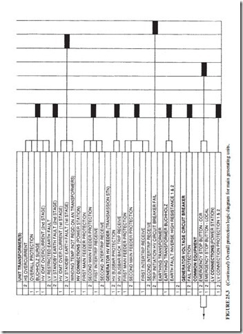
Figure 25.7 illustrates the overall protection logic diagram for a generating system. The group definitions are listed on the left-hand side of the drawings. They identify which
system should be tripped to bring the unit into a safe state. The logic diagram has the following format:
● The group 1 trips are category A. They require immediate opening of the generator high- voltage circuit breaker. This circuit breaker is located between the main generator and the generator transformer.
● The group 2 trips are also category A. They require immediate opening of the generator voltage circuit breaker to clear the fault. This circuit breaker is located between the gen- erator transformer and the grid. In this configuration, the generator will remain connected to the unit transformer.
● The group 3 trips are category B. They require opening of the generator high-voltage cir- cuit breaker on low forward power.
● The group 4 trips are also category B. They require opening of the generator voltage circuit breaker on low forward power.
Figure 25.7 illustrates the overall protection schematic diagram for the generating station. A number is associated with each trip-initiating device. This number is cross-referenced to Fig. 25.3. The group numbers are shown on both the tripping schematic and the logic diagram.


