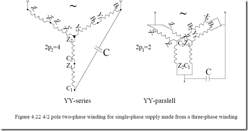
A 2/1 = 2p2/2p1 pole-changing winding for single-phase supply can be approached with a three-phase pole-changing winding. The Dahlander winding may be used (see Figure 4.16) as in Figure 4.22.
4.11. SPECIAL TOPICS ON A.C. WINDINGS
Most of the windings treated so far in this chapter are in industrial use today. At the same time, new knowledge has surfaced recently. Here we review the most significant part of it.
A new general formula for mmf distribution
Let us consider the slot opening angle β, ncK–conductors/slot/phase, iK(t) current in slot K, θK–slot position per periphery.
A linear current density in a slot IK(θK,t) may be defined as
I (θ,t)= 2ncKβD⋅iK ( )t for θ∈ θ( K −β/ 2,θK +β/ 2) (4.41) K
IK (θ,t)= 0 for θ∉ θ( K −β/ 2,θK +β/ 2)
For a single slot, the linear current density may be decomposed in mechanical harmonics as
IK (θ,t)= 2ncKπD⋅iK ( )t 12 + ∑∞ν K cosν (θ − θν) (4.42)
with Kν = ![]() sin
sin ![]() (4.43) The number ncK may be positive or negative depending on inward/outward sense of connections and it is zero if no conductors belong to that particular phase. By adding the contributions of all slots per phase A, we obtain its mmf [10,11].
(4.43) The number ncK may be positive or negative depending on inward/outward sense of connections and it is zero if no conductors belong to that particular phase. By adding the contributions of all slots per phase A, we obtain its mmf [10,11].
![]() with Kwν = 2W1 K 1∑N=s ncK cosνθK 2 + ∑Ns ncK sin νθK 2 (4.45)
with Kwν = 2W1 K 1∑N=s ncK cosνθK 2 + ∑Ns ncK sin νθK 2 (4.45)
1 K 1=
θAν = ν1 tan−1K 1∑N=s ncK sinνθK /K 1∑N=s ncK cosνθK (4.46)
where W1 is the total number of turns/phase. When there is more than one current path (a > 1), W1 is replaced by W1a (turns/phase/path) and only the slots/phase/path are considered.
Kwν is the total winding factor: spread and chording factors multiplied. This formula is valid for the general case (integer q or fractional q windings, included). The effect of slot opening on the phase mmf is considered through the factor Kν< 1(which is equal to unity for zero slot opening – ideal case). In general, in an ideal case, the mmf harmonics amplitude is reduced by slot opening, but so is its fundamental.
Low space harmonic content windings
Fractional pitch windings have been, in general, avoided for induction motor, especially due to low order (sub or fractional) harmonics and their consequences: parasitic torques, noise, vibration, and losses.
However, as basic resources for IM optimization are exhausted, new ways to reduce copper weight and losses are investigated. Among them, fractional windings with two pole symmetry (q = (2l + 1)/2) are investigated thoroughly [9,12]. They are characterised by the absence of sub (fractional) harmonics. The case of q = 3/2 is interesting low power motors for low-speed high-pole-count induction generators and motors. In essence, the number of turns of the coils in the two groups/phase belonging to neighboring poles (one with q1 = l and the other with q2 = l + 1) varies so that designated harmonics could reduce or destroy. Also, using coils of a different number of conductors in various slots of a phase with standard windings (say q = 2) should lead to the cancellation of low order mmf harmonics and thus render the motors less noisy.
A reduction of copper weight and (or) an increase in efficiency may thus be obtained. The price is using nonidentical coils.
The general formula of the winding factor (4.45) may be simplified for the case of q = 3/2, 5/2, 7/2 … where two-pole symmetry is secured and thus the summation in (4.45) extends along only two poles.
With γi the coil pitch, the winding factor Kwν, for two poles, is [9]
nci′ and ncK′ are relative numbers of turns with respect to total turns/polepair/phase; therefore the coil pitches may be different under the two poles. Also, the number of such coils for the first pole is q1 = l and for the second is q2 = l + 1 (q = (2l + 1)/2).
As q = (2l + 1)/2, the coil pitch angles γi will refer to an odd number of slot pitches while γK refers to an even number of slot pitches. So it could be shown that the winding factor Kwν of some odd and even harmonics pairs are equal to each other. For example, for q = 3/2, Kw4 = Kw5, Kw2 = Kw7, Kw1 = Kw8. These relationships may be used when designing the windings (choosing γi, γK and nci′, ncK′) to cancel some harmonics.
A quasisinusoidal two-layer winding [8]
Consider a winding with 2l + 1 coils/phase/pole pairs. Consquently, q = (2l + 1)/2 slot/pole/phase.
There are two groups of coils per phase. One for the first pole containing K + 1 coils of span 3l + 1, 3l – 1 … and, for the second pole, K coils of span 3l, 3l – 2. The problem consists of building a winding in two-layers to cancel all harmonics except those in multiples of 3 (which will be inactive in star connection of phases anyway) and the 3(2l + 1) ± 1, or slot harmonics.
∑Kwν(n ‘ nci + cK‘)= 0;ν = 2,4,5,…(in all 2l values) (4.48)
This linear system has a unique solution, which, in the order of increased number of turns, yields
n ‘ci = 4sin6 2( πl +1)sin (6 22(i −l +1)1π);i =1,2,3 2l +1 (4.50)
For the fundamental mmf wave, the winding factor Kw1 is
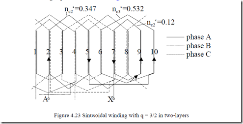
Kw1 = (2l+1) 3 sin 6 2( πl+1) (4.51) For l = 1, 2l +1 = 3 coils/phase/pole pair. In this case the relative number of turns per coil for phase A are (from 4.50): nc1′ = 0.1206, nc2′ = 0.3473, nc3′ = 0.5321.
As we can see, nc1′ + nc3′≅ 2 nc2′ so the filling of all slots is rather uniform though not identical.
The winding layout is shown in Figure 4.23.
The fundamental winding factor of this winding is Kw1 = 0.9023, which is satisfactory (both distribution and chording factors are included). To further cancel the multiples of 3 (3l) harmonics, two/three layer windings based on the same principle have been successfully tested [9] though their fundamental winding factor is below 0.8.
The same methodology could be applied for q = integer, by using concentrated coils with various numbers of turns to reduce mmf harmonics. Very smooth operation has been obtained with such a 2.2 kW motor with q = 2, 2p1 = 4, Ns = 24 slots up to 6000 rpm. [12]
In general, for the same copper weight, such sinusoidal windings are claimed to produce a 20% increase in starting torque and 5 to 8dB noise reduction, at about the same efficiency.
Better pole-changing windings
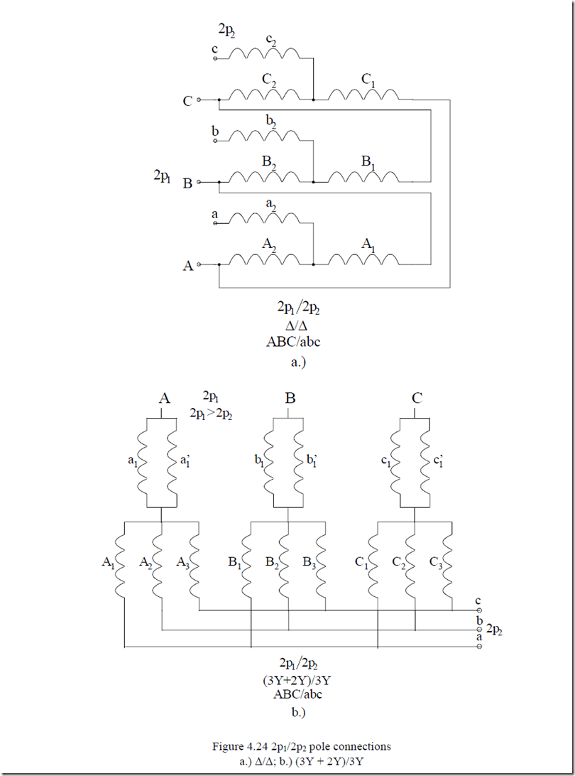
Pole amplitude modulation [3–5] and symmetrization [13–14] techniques have been introduced in the sixties and revisited in the nineties. [15] Like interspersing [10, pp.37–39], these methods have produced mixed results so far. On the other hand, the so called ”3 equation principle” for better pole-changing winding has been presented in [7] for various pole count combinations. This is also a kind of symmetrization method but with a well defined methodology. The connections of phases is ∆/∆ and (3Y +2Y)/3Y for 2p2and 2p1 pole counts, respectively. Higher fundamental winding factor, lower harmonics content, better winding and core utilisation, and simpler switching devices from 2p2 to 2p1 poles than with Dahlander connections are all merits of such a methodology.
Two single-throw switches (soft starters) suffice (Figure 4.24) to change speed.
+ Ns + 2Ns/3 are in phase and thus belong to the same phase and we may build three parallel branches (paths) per phase in a 3Y connection (Figure 4.24b). In general, n = 1, 2, … Ns/3.
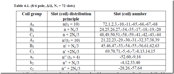
As already meantioned, the ∆/∆ connection (Figure 4.24a) is typical for nonmultiple of 3 pole counts (2p1/2p2 = 8/10, for example). Suppose every coil group A1,2,3, B1,2,3, C1,2,3 is made of t1 coils (t1< Ns/6). The coil group A1 is made of t1 coils in slots n1, n2, …, nt1 while groups B1 and C1 are displaced by Ns/3 and 2Ns/3, respectively. The sections A1, B1, C1, which belong to the three-phases, do not change phase when the number of poles is changed from 2p1 to 2p2.
On the other hand, coil groups A2, B2, C2 are composed of t2< Ns/6 coils and thus coil group A2 refers to slots n1′, n2′, …, nt2′ while coil groups B2 and C2 are displaced by Ns/3 and 2Ns/3 with respect to group A2. Again, sections A2, B2, C2 are symmetric.
It may be shown that for 2p1 and 2p2 equal to 2p1 = 6K1 + 2(4) and 2p2 = 6K2 + 1, respectively, the mmf waves for the two pole counts travel in the same direction.
On the other hand, if 2p1 = 6K1 + 2(4) and 2p2 = 6K2 + 4(2), the mmf waves for the two pole counts move in opposite directions. Swapping two phases is required to keep the same direction of motion for both pole counts (speeds). In general, t1 or t2 are equal to Ns/6. For voltage adjustment for higher pole counts, t3 = Ns/3-ti slots/phase are left out and distributed later, also with symmetry in mind.
Adjusting groups of t3 slots/phase should not produce emfs phase shifted by more than 300 with respect to groups AiBiCi to secure a high spread
(distribution) factor.
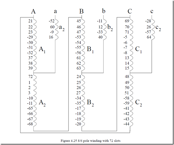
An example of such an 8/6 pole ∆/∆ winding is shown in Table 4.1 [7]; the coil connections from table 4.1 are shown in Figure 4.25. [7]
Such a pole-changing winding seems suitable for fan or windmill applications as the power delivered is reduced to almost half when switching from 8 to 10 poles, that is, with a 20% reduction in speed. The procedure is similar for the (3Y + 2Y)/3Y connection. [6]
This type (Figure 4.24b) for a1 = a1′ = b1 = b1′ = c1 = c1′ = 0 and pole count ratio of say 2p2/2p1 = 6/2 has long been known and recently proposed for dual winding (doubly fed) stator nest – cage rotor induction machines [16].
Once the slot/phase allocation is completed the general formula for the winding factor (4.45) or the mmf step-shape distribution with harmonics decomposition may be used to determine the mmf fundamental and harmonics content for both pole counts. These results are part of any IM design process.
A pure mathematical approach to a.c. winding design
As we have seen so far, a.c. winding design is more an art than a science. Intuition and symmetry serve as tools to this aim.
Since we have a general expression for the harmonics winding factor valid for all situations when we know the number of turns per coil and what current flows through those coils in each slot, we may develop an objective function to define an optimum performance.
Maximum airgap flux energy for the fundamental mmf, or minimum of some harmonics squared winding factors summation, or the maximum fundamental winding factor, may constitute practical objective functions. Now copper weight may be considered a constraint. So is the pole count 2p1. Some of
the above objectives may become constraints. What then would the variables be for this problem? It seems that the slot/phase allocation and ultimately, the number of turns/coil are essential variables to play with, together with the number of slots.
In a pole-changing (2p2/2p1) winding, the optimization process has to be done twice. This way the problem becomes typical: non-linear, with constraints. All optimization methods used now in electric machine design also could apparently be applied here.
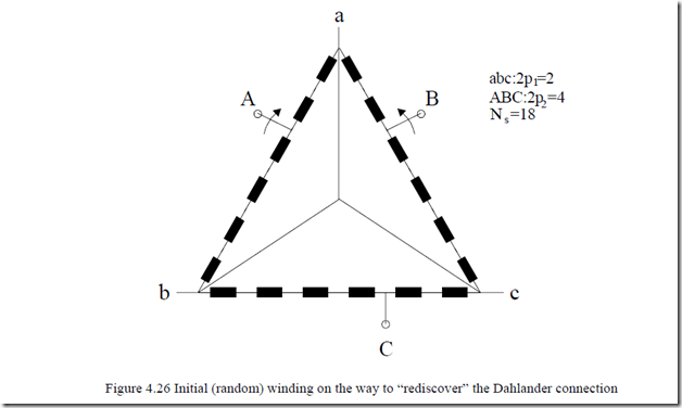
The first attempt has been made in [7] by using the “simulated annealing method”–a kind of direct (random) search method, for windings with identical coils. The process starts with fixing the phase connection: Y or ∆ and with a random allocation of slots to phases A, B, C. Then we take the instant when the current in phase A is maximum iMax and iB = iC = −iMax/2. Allowing for a given number of turns per coil nc and 1 or 2 layers, we may start with given (random) mmfs in each phase.
Then we calculate the objective function for this initial situation and proceed to modify the slot/phase allocation either by changing the connection (beginning or end) of the coil or its position (see Figure 4.26). Various rules of change may be adopted here.
The objective function is calculated again. The computation cycle is redone until sufficient convergence is obtained for a limited computation time.
In [7] by using such an approach the 4/2 pole Dahlander connection for an 18 slot IM is rediscovered after two hours CPU time on a large main frame computer. The computer time is still large, so the direct (random) search approach has to be refined or changed, but the method becomes feasible, especially for some particular applications.
