RELAYS AND SWITCHES
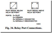
In the following illustrations, common (C) and the normally connected port (O) are connected on a fall in pilot pressure (P) below the relay setpoint, and the normally disconnected port (X) is blocked (Fig. 34). On a rise in pilot pressure above the relay setpoint, C and X are connected and O is blocked.
A switching relay requires a two-position pilot signal and is available with either single-pole, double-throw (spdt) or double-pole, double-throw (dpdt) switching action. Pneumatic heating and cooling control systems use relays to switch a valve or damper actuator from one circuit to another or to positively open or close a device. Both spdt and dpdt switching relays are available with a variety of switching pressures.
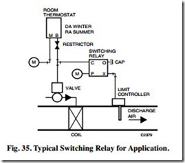
Figure 35 shows a typical spdt switching relay application for heating/cooling operation in which the thermostat controls the heating/cooling coil valve. Seasonal mainline pressure changes cause the action of the thermostat to be reversed. A discharge low-limit control is switched into the control circuit for heat- ing and out of the circuit for cooling. The switching is done from mainline pressure connected to the pilot port (P).
During the heating cycle, the 18 psi mainline pressure is above the preset switching pressure. The common port (C) connects to the normally disconnected port (X), connecting the low-limit controller to the thermostat branchline to prevent discharge temperatures below the controller setting. The normally connected port (O) is blocked.
During the cooling cycle, the 13 psi mainline pressure at the pilot port (P) is below the minimum switching pressure of the preset limits. The common port (C) connects to the normally connected port (O), which is capped. The normally disconnected port (X) is closed and removes the low-limit controller from the system.
In a dpdt model, the common, normally connected, and normally disconnected ports are duplicated in the second switch section.
SNAP ACTING RELAY
The snap acting relay is a spdt switch that provides two- position switching action from a modulating signal and has an adjustable switching point. The switching differential is less than 1.0 psi. The switching pressure is manually adjustable for 3 to 15 psi operation.
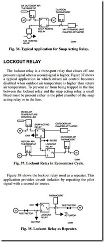
Figure 36 shows a snap acting relay application. Operation is similar to the switching relay. When the branchline pressure from the outdoor air thermostat equals or exceeds the preset switchover pressure, the relay connects the normally disconnected port (X) and blocks the normally connected port (O) to deliver main air to the normally open heating valve and provide positive close off. When the outdoor air thermostat pressure drops below the relay setpoint, the normally disconnected port (X) is blocked and the normally connected port (O) connects to the common port (C) to connect the valve actuator to the room thermostat.
CAPACITY RELAY
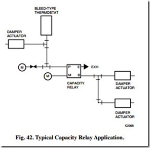
The capacity relay is a direct-acting relay that isolates an input and repeats the input pressure with a higher capacity output. Figure 42 shows a capacity relay enabling a single bleed-type thermostat to operate multiple damper actuators quickly by increasing the output capacity of the thermostat.
REVERSING RELAY
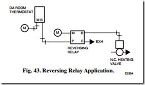
The reversing relay is a modulating relay with an output that decreases at a one-to-one ratio as the input signal increases. Figure 43 shows a reversing relay application. A falling temperature at the direct-acting thermostat causes the branchline pressure to decrease. The reversing relay branch pressure increases and opens the normally closed heating valve.
POSITIVE-POSITIONING RELAY
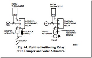
The positive-positioning relay (Fig. 44) mounts directly on a valve or damper actuator. The relay positions the valve or damper precisely according to the branchline pressure from a thermostat or other controller, regardless of the load variations affecting the valve stem or damper shaft. The relay is typically used for large actuators for sequencing, or in applications requiring precise control.
When the relay is connected to an actuator, the feedback spring produces a force proportional to the actual valve or damper position. The relay positions the actuator in proportion to the branchline input. If the connected load attempts to unbalance the required valve stem position, the relay either exhausts or applies main pressure to the actuator to correct the condition. If the valve or damper sticks or the load prevents proper positioning, the relay can apply the pressure required (up to full main pressure) or down to zero to correct the condition.
The positive-positioning relay also permits sequenced operation of multiple control valves or dampers from a single thermostat or controller. For example, a normally open heating valve and a normally closed outdoor air damper could be controlled from a single thermostat piloting relays on two actuators. Relays typically have a 3, 5, or 10 psi input pressure span and an adjustable start pressure. As the space temperature rises into the low end of the thermostat throttling range, the heating valve positioner starts to close the valve.
AVERAGING RELAY
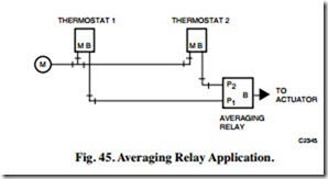
The averaging relay is a direct-acting, three-port relay used in applications that require the average of two input pressures to supply a controller input or to operate a controlled device directly.
Figure 45 shows an averaging relay in a typical application with two thermostat signals as inputs. The average of the thermostat signals controls a valve or damper actuator.
RATIO RELAY
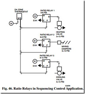
The ratio relay is a four-port, non bleed relay that produces a modulating pressure output proportional to the thermostat or controller branchline output. Ratio relays can be used to control two or three pneumatic valves or damper actuators in sequence from a single thermostat. The ratio relay has a fixed input pressure range of either 3 or 5 psi for a 10 psi output range and an adjustable start point. For example, in a ratio relay with a 5 psi range set for a 7 psi start, as the input pressure varies from 7 to 12 psi (start point plus range), the output pressure will vary from 3 to 13 psi.
In Figure 46, three 3 psi span ratio relays are set for 3 to 6, 6 to 9, and 9 to 12 psi inputs, respectively. The thermostat signal through the relays proportions in sequence the three valves or actuators that have identical 3 to 13 psi springs.
PNEUMATIC POTENTIOMETER
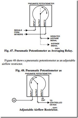
The pneumatic potentiometer is a three-port, adjustable linear restrictor used in control systems to sum two input signal values, average two input pressures, or as an adjustable flow restriction. The potentiometer is a linear, restricted air passage between two input ports. The pressure at the adjustable output port is a value based on the inputs at the two end connections and the location of the wiper between them.
Figure 47 shows a pneumatic potentiometer providing an average of two input signals. The wiper is set at mid-scale for averaging or off-center for a weighted average. It can be used this way to average two air velocity transmitter signals from ducts with different areas by positioning the wiper according to the ratio of the duct areas. This outputs a signal proportional to the airflow.
HESITATION RELAY
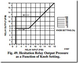
The hesitation relay is used with a pneumatic actuator in unit ventilator applications. The output pressure goes to minimum whenever the input pressure is below the minimum setting. Figure 49 shows a graph of the output of a hesitation relay as controlled by the relay knob settings (piloted from the thermostat).
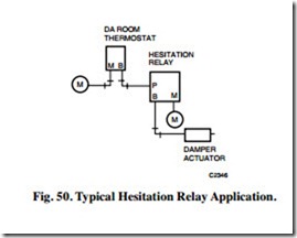
The hesitation relay has an internal restrictor. Figure 50 shows a typical application of a hesitation relay and a pneumatic damper actuator. When the thermostat branchline pressure reaches 1.5 psi, the relay output goes to its preset minimum pressure. When the branchline pressure of the thermostat reaches the setting of the hesitation relay, the thermostat controls the damper actuator. When the thermostat branchline pressure drops below the hesitation relay setting, the relay holds the damper actuator at the minimum position until the thermostat branchline pressure drops below 1.5 psi. At that point, the hesitation relay output falls to zero.
ELECTRICAL INTERLOCKING RELAYS
Electrical interlocking relays bridge electric and pneumatic circuits. The electric-pneumatic relay uses electric power to actuate an air valve in an associated pneumatic circuit. The pneumatic-electric relay uses control air pressure to make or break an associated electrical circuit.
ELECTRIC-PNEUMATIC RELAY
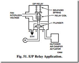
The electric-pneumatic (E/P) relay is a two-position, three- way air valve. Depending on the piping connections to the ports, the relay performs the same functions as a simple diverting relay. A common application for the E/P relay is to exhaust and close an outdoor air damper in a fan system when the fan motor is turned off, as shown in Figure 51.
When the relay coil is de-energized, the solenoid spring seats the plunger. The normally disconnected port (X) is blocked and the normally connected port (O) connects to the common port (C). The connection exhausts the damper actuator which closes the damper. When the relay coil is energized, the plunger lifts against the tension of the spring and blocks the normally connected port (O). Main air at the normally disconnected port (X) connects to the common port (C) and opens the damper.
PNEUMATIC-ELECTRIC RELAY
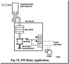
Figure 52 shows a simplified pneumatic-electric (P/E) relay with a spdt switch. The P/E relay makes the normally closed contact on a fall in pilot pressure below the setpoint, and makes the normally open contact on a rise above a value equal to the setpoint plus the differential. For example, with a setpoint adjustment of 3 psi and a differential of 2 psi, the pump is energized at pilot pressures below 3 psi and turns off at pilot pressures above 5 psi.
ELECTRONIC-PNEUMATIC TRANSDUCER
The electronic-pneumatic transducer is a proportional relay that varies the branch air pressure linearly 3 to 15 psi in response to changes in an electrical input of 2 to 10 volts or 4 to 20 ma. Electronic-pneumatic transducers are used as the interface between electronic, digital, or computer-based control systems and pneumatic output devices (e.g., actuators).
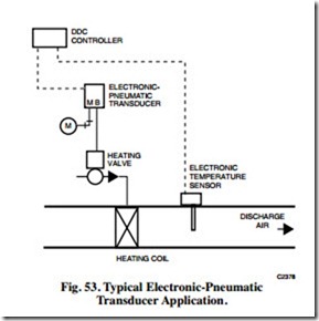
Figure 53 shows discharge air temperature control of a heating coil using digital control for sensing and control. The output of the transducer positions the valve on a heating coil.
A resistance-type temperature sensor in the discharge air duct is the input to the controller, which provides all of the system adjustments and logic requirements for control. The controller output of 2 to 10 volts dc is input to the electronic- pneumatic transducer, which converts the signal to a 3 to 15 psi output to position the heating valve.
PNEUMATIC SWITCH
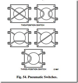
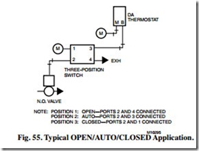
The pneumatic switch is available in two- or three-position models (Fig. 54). Rotating the switch knob causes the ports to align in one of two ways in a two-position switch, and in one of three ways in a three-position switch. The two-position switch is used for circuit interchange. The three-position switch sequentially switches the common port (Port 2) to the other ports and blocks the disconnected ports.
Figure 55 shows a typical application for sequential switching. In the OPEN position, the valve actuator exhausts through Port 4 and the valve opens. In the AUTO position, the actuator connects to the thermostat and the valve is in the automatic mode. In the CLOSED position, the actuator connects to main air and the valve closes.
MANUAL POSITIONING SWITCH
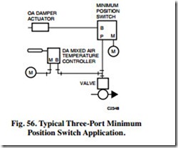
A manual positioning switch is used to position a remote valve or damper or change the setpoint of a controller. The switch takes input air from a controller and passes a preset, constant, minimum air pressure to the branch regardless of the controller output (e.g., to provide an adjustable minimum position of an outdoor air damper). Branchline pressure from the controller to other devices connected to the controller is not affected.
Figure 56 shows the switch functioning as a minimum positioning switch. The damper will not close beyond the minimum setting of the positioning switch. As the controller signal increases above the switch setting, the switch positions the damper according to the controller signal.
Manual switches are generally panel mounted with a dial plate or nameplate on the front of the panel which shows the switch position. Gages are sometimes furnished to indicate the main and branch pressures to the switch.
