Magnetic Overload Relays
Magnetic type overload relays operate by sensing the strength of the magnetic field produced by the current flowing to the motor. The greatest difference between magnetic type and thermal type overload re- lays is that magnetic types are not sensitive to ambient temperature. Magnetic type overload relays are generally used in areas that exhibit extreme changes in ambient temperature. Magnetic overload relays can be divided into two major types: electronic and dashpot.
Electronic Overload Relays
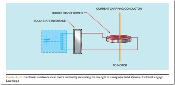
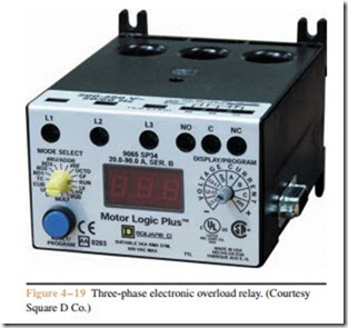
Electronic overload relays employ a current trans- former to sense the motor current. The conductor that supplies power to the motor passes through the core of a toroid transformer (Figure 4 – 18). As current flows through the conductor, the alternating magnetic field around the conductor induces a voltage into the toroid transformer. The amount of induced voltage is proportional to the amount of current flowing through the conductor. This is the same basic principle of operation employed by most clamp-on type ammeters. The volt- age induced into the toroid transformer is transmitted through a connected electronic interface that provides the time delay necessary to permit the motor to start. Many electronic type overload relays are programmable and can be set for the amount of full load motor current, maximum and minimum voltage levels, percentage of overload, and other factors. A three-phase electronic overload relay is shown in Figure 4 – 19.
Dashpot Overload Relays
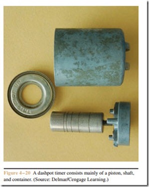
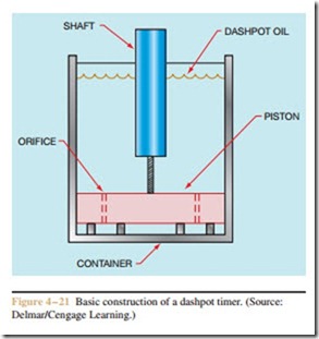
Dashpot overload relays receive their name from the device used to accomplish the time delay that permits the motor to start. A dashpot timer is basically a container, a piston, and a shaft (Figure 4 – 20). The piston is placed inside the container, and the container is filled with a special type of oil called dashpot oil (Figure 4 – 21). Dashpot oil maintains a constant viscosity over a wide range of temperatures. The type and viscosity of oil used is one of the factors that determine
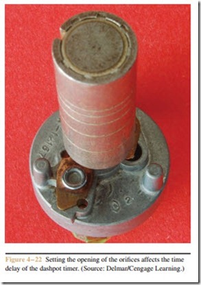
the amount of time delay for the timer. The other factor is the setting of the opening of the orifice holes in the piston (Figure 4 – 22). Orifice holes permit the oil to flow through the piston as it rises through the oil. The opening of the orifice holes can be set by adjusting a sliding valve on the piston.
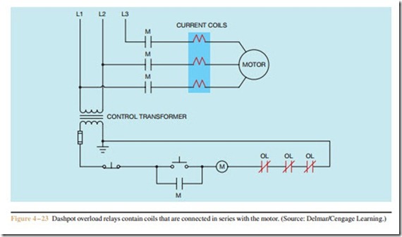
The dashpot overload relay contains a coil that is connected in series with the motor (Figure 4 – 23). As current flows through the coil, a magnetic field is developed around the coil. The strength of the magnetic field is proportional to the motor current. This magnetic field draws the shaft of the dashpot timer into the coil. The shaft’s movement is retarded by the fact that the piston must displace the oil in the container. If
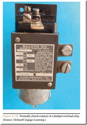
the motor is operating normally, the motor current will drop to a safe level before the shaft is drawn far enough into the coil to open the normally closed contact (Fig- ure 4 – 24). If the motor is overloaded, however, the magnetic field will be strong enough to continue draw- ing the shaft into the coil until it opens the overload contact. When power is disconnected from the motor, the magnetic field collapses and the piston returns to the bottom of the container. Check valves permit the piston to return to the bottom of the container almost immediately when motor current ceases.
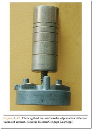
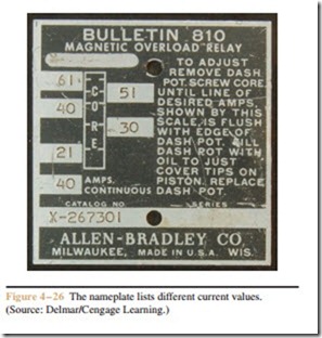
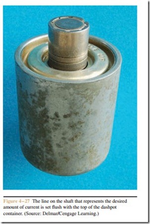
Dashpot overloads generally provide some method that permits the relay to be adjusted for different full load current values. To make this adjustment, the shaft is connected to a threaded rod (Figure 4 – 25). This permits the shaft to be lengthened or shortened inside the coil. The greater the length of the shaft, the less current is required to draw the shaft into the coil far enough to open the contacts. A nameplate on the coil lists the different current settings for a particular overload relay (Figure 4 – 26). The adjustment is made by moving the
shaft until the line on the shaft representing the desired current is flush with the top of the dashpot container (Figure 4 – 27). A dashpot overload relay is shown in Figure 4 – 28.
