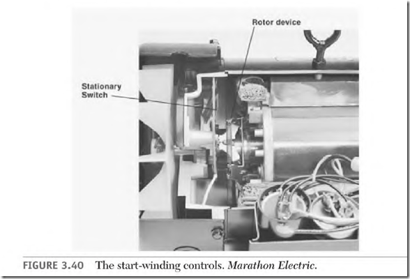
The capacitor-start motor starts the same as a two-phase motor. But, unlike two-phase power, which has two voltages, there is only one voltage applied. Single-phase power is applied to both the start and run windings to start the motor. About I second after power is applied, the rotor should be turning between 75 and 80 percent of synchronous speed. At this time a switch (Fig. 3.40) disconnects the start winding.
The motor now runs on only the run (main) winding. With rated load applied, the rotor pulls the load at or near its nameplate RPM. With no load![]()
the rotor will turn at nearly synchronous RPM. (The load determines the exact speed of the motor.)
The capacitor-start and three-phase induction motors both have squirrel cage rotors. To better understand how the rotor gets its power, transformer theory must first be understood.
Transformer Theory
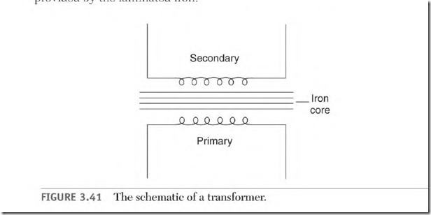
A transformer is a device used to transfer the power of alternating current from one circuit to another without a direct electrical connection. Figure 3.41 is a schematic of a transformer.
Transformer Components
A transformer consists of a primary winding, a secondary winding, and a laminated iron core.
The primary winding is connected to an AC power source. It transforms power to the secondary winding. The secondary winding is on the load side of the device. The laminated iron carries the magnetic flux of the primary winding to the secondary winding.
Voltage applied to the primary winding creates a continually changing current in its circuit. The changing current creates a magnetic field in the iron core, which is changing at the same rate. The laminated core’s magnetic flux cuts the conductors of the secondary winding, transforming a voltage into it. The only connection between the two windings is the magnetic link provided by the laminated iron.
Transformer Function
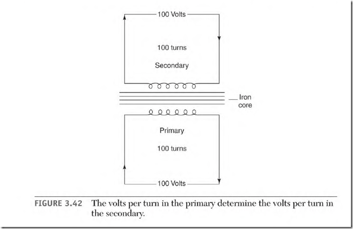
Assuming there are no losses, the same voltage value of each turn of the primary winding is transformed into each turn of the secondary winding. In the design of most transformers, 5 to 8 percent more turns are added to the secondary winding to account for any losses.
Volts Per Turn
The primary coil (Fig. 3.42) has 100 turns with 100 volts applied to it: 100 volts + 100 turns of the primary coil = 1 volt per turn in the primary coil. Each turn of the secondary coil will have 1 volt transformed into it. The voltage value of each turn in the secondary is added to the next turn because they are wound in the same direction. If there are 100 turns in the secondary coil, its voltage output is 100 volts: 10 turns — 10 volts, 1 turn = 1 volt, 200 turns = 200 volts, and so on.
Transformer Rating
Power for the load is furnished by the primary winding when a load is applied to the secondary winding. Although the voltage and amperes of the
primary and secondary may vary, the watts—assuming there are no losses— are the same in both windings. The watt load of the primary is determined by the load applied to the secondary.
The physical size (amount of iron and wire size) of a transformer is determined by its power rating. Thansformers and motors are similar in this respect. In the United States, transformers are rated in VA or KVA (volts x amps or volts x amps — 1000) and electric motors are rated in horsepower. In Europe, both transformers and electric motors are rated in voltamperes or kilovoltamperes (VA or KVA).
For example (with no losses):
Primary load is 1000 watts @ 100 volts
Secondary load is 1000 watts @ 10 volts
Primary winding: 1000 watts . 100 volts![]()
10 amperes in the primary winding
Secondary winding: 1000 watts 10 volts —
100 amperes in the secondary winding
Thansformers are designed to step the voltage up or down, or to isolate the power, with no change in voltage value. Hertz is not changed by a transformer.
Solder Gun Transformer
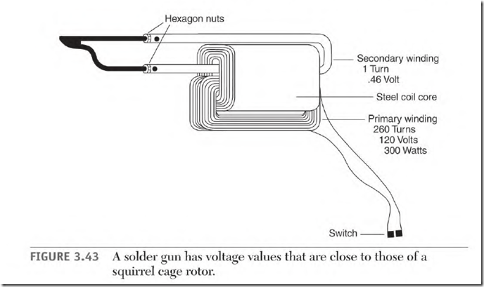
A solder gun makes a good model for transformer theory. The power values and problems are similar to those of the squirrel cage rotor of an induction motor.
Figure 3.43 shows a solder gun and its components, a primary winding, a secondary winding, and laminated iron (which forms a magnetic link between the two windings). The solder gun data is 120 volts and 300 watts, and has 260 turns in the primary coil and one turn in the secondary one.
The formula for volts per turn is
Volts + turns = volts per turn
The formulas for watts are
Volts x amps —— watts
Watts + amps — volts
Watts + volts —— amps
Primary volts per turn and amperes formulas are
120 volts 260 turns = 0.46 volt per turn (primary)
300 watts — 120 volts = 2.5 amperes (primary)
The formulas for secondary volts per turn and amperes are
1 turn = 0.46 volt
300 watts + 0.46 volt = 652 amps
0.46 volt — 652 amps = 0.0007 ohm (resistance of the soldering tip)


