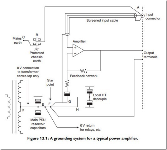
Amplifier Grounding
The grounding system of an amplifier must fulfil several requirements, among which are:
● The definition of a starpoint as the reference for all signal voltages.
● In a stereo amplifier, grounds must be suitably segregated for good cross talk performance. A few inches of wire as a shared ground to the output terminals will probably dominate the cross talk behavior.
● Unwanted AC currents entering the amplifier on the signal ground, due to external ground loops, must be diverted away from the critical signal grounds, that is, the input ground and the ground for the feedback arm. Any voltage difference between these last two grounds appears directly in the output.
● Charging currents for the power supply unit (PSU) reservoir capacitors must be kept out of all other grounds.
Ground is the point of reference for all signals, and it is vital that it is made solid and kept clean; every ground track and wire must be treated as a resistance across which signal currents will cause unwanted voltage drops. The best method is to keep ground currents apart by means of a suitable connection topology, such as a separate ground return to the starpoint for the local HT decoupling, but when this is not practical it is necessary to make every ground track as thick as possible and fattened up with copper at every possible point. It is vital that the ground path has no necks or narrow sections, as it is no stronger than the weakest part. If the ground path changes board side then a single via hole may be insufficient, and several should be connected in parallel. Some CAD systems make this difficult, but there is usually a way to fool them.
Power amplifiers rarely use double-insulated construction and so the chassis and all metalwork must be grounded permanently and solidly for safety. One result of permanent chassis grounding is that an amplifier with unbalanced inputs may appear susceptible to ground loops. One solution is to connect audio ground to chassis only through a 10-Ω resistor, which is large enough to prevent loop currents becoming significant. This is not very satisfactory as:
● The audio system as a whole may not be grounded solidly.
● If the resistor is burnt out due to misconnected speaker outputs, the audio circuitry is floating and could become a safety hazard.
● The RF rejection of the power amplifier is likely to be degraded. A 100-nF capacitor across the resistor may help.
A better approach is to put the audio-chassis ground connection at the input connector so that in Figure 13.1, ground-loop currents must flow through A–B to the protected earth at B and then to mains ground via B–C. They cannot flow through the audio path E–F. This
topology is very resistant to ground loops, even with an unbalanced input; the limitation on system performance in the presence of a ground loop is now determined by the voltage drop in the input cable ground, which is outside the control of the amplifier designer.
A balanced input could, in theory, cancel out this voltage drop completely.
Figure 13.1 also shows how the other grounding requirements are met. The reservoir charging pulses are confined to the connection D–E and do not flow E–F, as there is no other circuit path. E–F–H carries ripple, etc., from the local HT decouplers, but likewise cannot contaminate the crucial audio ground A–G.
