NETWORK ROUTERS
Overview
A network router is a computer networking device that forwards electronic digital data or signals within a network or between separate networks. It will be connected to at least two networks or at least
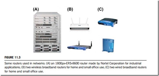
two subnetworks that can be LANs (local area network), WANs (wide area network), corporate or enterprise networks, Internets or ISP (Internet service provider) networks, and home or small office networks. As mentioned before, routers are assumed to work with the layer 3, the network layer, of the OSI model. The term layer 3 switch is thus used interchangeably with network router, but switch is really a marketing term without a rigorous technical definition. Figure 11.3 shows some network routers.
A router takes information from multiple sources and routes it to multiple destinations within networks or subnetworks, typically being used to send data packets to the destination’s data terminal equipment. A network is a collection of interconnected electronic devices which allow users to access resources and data. Networks can include the nodes themselves, a connecting medium (wired, wireless and/or a combination of wired and wireless), and network switching systems such as routers, hubs and/ or switches. The nodes typically communicate by exchanging discrete frames or packets of data according to predefined protocols. In a packet-based network, such as the Internet, the computing devices communicate by dividing the data into small blocks called packets which are individually routed across the network from source to destination. The destination device extracts the data from the packets and assembles it back into its original form. Dividing the data into packets enables the source device to resend only those individual packets that may be lost during transmission.
Traditional routers are designed to join multiple area networks (LANs and WANs). On the Internet or on a large corporate network, for example, routers serve as intermediate destinations for network traffic. Routers for home networks (often called broadband routers) are designed specifically to join the home (LAN) to the Internet (WAN) for the purpose of Internet connection sharing. These routers receive TCP/IP packets, look inside each packet to identify the source and target IP addresses, and then forward them to their final destination. However, in the larger company or enterprise, routers are also used to separate LANs into subnetworks in order to balance traffic within workgroups, and to filter traffic for security purposes and policy management. Here, routers serve as an internet backbone that connects all internal networks, usually via Ethernet. Within the global Internet, routers do all the packet switching between the backbones and are typically connected via ATM (asynchronous transfer mode) or SONET (synchronous optical network). Furthermore, routers often contain a built-in firewall for security, which serves all users in the network without requiring that the personal firewall in each computer be turned on and configured.
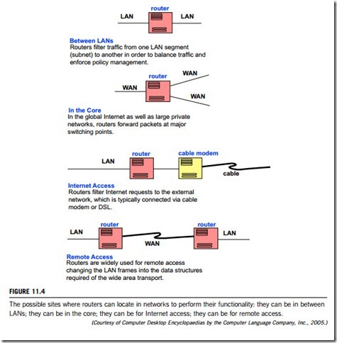
Figure 11.4 shows the sites where routers can be located in the computer network to perform their functionality i.e. in between LANs; in the core; for Internet or for remote access.
A network router is a more sophisticated network device than either a switch or a hub. The functions of a router, hub and a switch are all quite different from one another, even if at times they are all integrated into a single device. Where a hub or switch is concerned with transmitting data packets,
(Courtesy of Computer Desktop Encyclopaedias by the Computer Language Company, Inc., 2005.)
the job of a router is to route packets to other networks until that packet ultimately reaches its destination, given by address of where it is going held within the packet.
In contrast, neither hubs nor switches are capable of joining multiple networks or sharing an Internet connection. A home network with only hubs and switches must designate one computer as the gateway to the Internet, and that device must possess two network adapters for sharing, one for the home LAN and one for the Internet WAN. With a router, all home computers connect to the router equally, and it performs the equivalent gateway functions. Routers, like bridges, provide bandwidth control (also termed data flow control) by keeping data out of subnetworks where they do not belong. However, routers, once set up, can communicate with other routers and learn the way to parts of a network that have been added after it was initially configured.
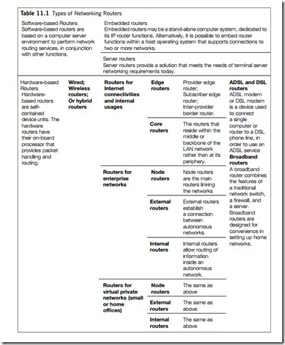
Routers differ slightly from network to network, so are now available in many types, though all fundamentally play the same role in a network. What defines a router is not its shape, color, size or manufacturer, but how it routes data packets between network computers and devices. Table 11.1 lists all the types of routers used today.
Router operations, specifications and configurations
Routers operate in two different phases; the control phase and the forwarding phase and require supporting hardware and software. Router hardware physically connects separate computer networks, and is responsible for routing the network information from source to destination. Router software is used to determine the point-to-point switching in the network information path, and is used to determine each path taken on the network. When used in a network, routers need to be configured, to verify that their hardware and software can adapt to the network.
(1) Router operation phases
Routers implement their operations in terms of two work phases: the control phase and the forwarding phase.
(a) Control phase
The control phase constructs the routing table from knowledge of the up and down status of its local interfaces, from hard-coded static routes, and from exchanging routing protocol information with other routers. It is not compulsory for a router to use routing protocols to function, if for example it was configured solely with static routes. Several different information sources may provide information on a route to a given destination, but the router must select the “best” route to install into the routing table. In some cases, there may be multiple routes of equal quality, and the router may install all of them and load-share across them.
In routing, the control phase is concerned with drawing the network map, or the information in a (possibly augmented) routing table that defines what to do with incoming packets. Control phase logic can also define certain packets to be discarded, as well as preferential treatment of certain packets for which a high quality of service is required by such mechanisms as differentiated services.
A major function of the control phase is to decide which routes go into the main routing table. Here the term main refers to the table that holds the active unicast routes. If the router also does multicast routing, there may be an additional routing table for these routes.
(b) Forwarding phase
This performs the pure Internet Protocol (IP) forwarding function. In routing, the forwarding phase decides what to do with packets arriving on an inbound interface. Most commonly, it refers to a table to look up the destination address of the incoming packet and retrieves the path from the receiving element, through the internal forwarding fabric of the router, and to the proper outgoing interface(s).
As mentioned above, the routing table also might specify that the data packet is discarded. In some cases, the router will return an ICMP (Internet Control Message Protocol) “destination unreachable” or other appropriate code. Some security policies, however, dictate that the router should be programmed to drop the packet silently, in order to keep a potential attacker from becoming aware of a target that is being protected. Depending on the specific router implementation, the routing table in which the destination address is looked up could be the routing table, or a separate forwarding information base that is populated (i.e., loaded) by the control phase, but used by the forwarding phase to look up packets and decide how to handle them. Before or after examining the destination, other tables may be consulted to make decisions to drop the packet based on other characteristics, such as the source address, the IP protocol identifier field, or TCP or UDP port number.
In general, the passage from the input interface directly to an output interface, through the fabric with minimum modification at the output interface, is called the fast path of the router. If the packet needs significant processing, such as segmentation or encryption, it may go onto a slower path, which is sometimes called the services phase of the router.
(2) Router hardware components
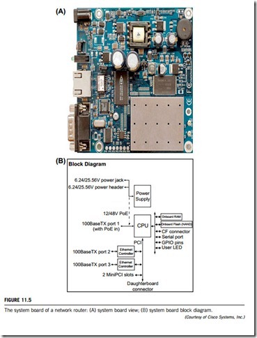
Routers are nothing more than a special type of personal computer (PC). Routers and computers both have some of the same components, such as a microprocessor, motherboard, RAM, interface boards, and an operating system. The main difference between a router and a standard PC is that the former performs special tasks to control or “route” traffic between two or more networks. There are seven major internal components of a router: CPU, RAM, NVRAM, Flash, ROM, console, and interfaces. The view and block diagram of a router system board are given in Figure 11.5.
(a) CPU
The CPU performs the same functions as in a normal PC. It executes commands given by the IOS (input/output system) by using other hardware components. High-end routers may contain multiple processors or extra slots to add more CPUs.
(b) RAM
The main roles of the RAM are to hold the ARP (address resolution protocol) cache, to store routing tables, to hold fast-switching cache, to perform packet buffering, and to hold queues. It also provides temporary memory for the configuration file of the router while it is powered on. However, the RAM loses content when the router is restarted or powered off. Please note that this component is upgradeable.
(c) NVRAM
Nonvolatile RAM is used to store the start-up configuration files. This type of RAM does not lose its content when the router is restarted or powered off.
(d) Flash
Flash memory saves data flows if the operating system configuration is disrupted. It holds the IOS image file, as well as backups. This flash memory is classified as an EEPROM (electronically erasable programmable read only memory), and is upgradeable in most Cisco routers.
(e) ROM
The ROM performs the same operations as the BIOS (basic input/output system). It holds information about the system’s hardware components and runs POST (power on self test) when the router first starts up. This component can be upgraded by unplugging the chip and installing a new one.
(f) Console
The console consists of the physical plugs and jacks on the router. It provides access for configuration.
(g) Interfaces
The interfaces provide connectivity to LAN, WAN, and console. They can be jacks soldered onto the motherboard, transceiver modules, or card modules. Routers, especially the higher-end models, can be configured in many different ways. They can use a combination of transceivers, card modules and onboard interfaces.
(3) Router software components
A router’s software package must include a real-time operating system (RTOS) to provide the basic command functions for the routing device as well as various subsystem components. In addition to the RTOS, routers generally organize their software into a management plane, input/output plane, control plane, and forwarding plane.
(a) Management plane
The management plane oversees the router in processing its routing functions. Its responsibilities include configuring the forwarding paths, scheduling other planes’ operations, monitoring the packet routing status, and handling possible traffic congestion and data errors.
(b) Input/output plane
The input/output plane works as a device driver to manage input/output interfaces at each driver and slot level, and as a handler for configuration, status reporting and statistics. It is typically embedded into the RTOS of the router, to ensure that it requires modest CPU and memory resources.
(c) Control plane
The control plane is the largest and most challenging software component in a router, since it is responsible for the implement of routing protocols, data-link layer protocols, and gateway to off-box services. This software component must, therefore scale in terms of physical and logical (subscriber) interface count, routing protocol peers, and route and prefix counts, and the off-box services trans- actions per second. This component is also required to have a very rich feature set with high feature velocity, and some real-time capabilities.
(d) Forwarding plane
The forwarding plane manages the hardware for the forwarding function including building tables, trees, classification tables, etc. as required to process packets and apply features. It also gathers statistics and state from forwarding plane hardware. It can require significant CPU and memory resources because scale, performance and real-time response are important requirements.
(4) Router performance specifications
Specification parameters include number of ports, data rate, and memory. Number of ports specifies the total number of ports available on the networking equipment. Data rate is the maximum data transfer speed. Memory is the total memory capacity of the network equipment. Common port choices for network routers include IEEE 1394, RJ-45, serial, ISDN, and USB. Features for network routers include stackability, rack mounting, LED indicators, integrated firewall, IP addressing, and VPN (virtual private network). Routers that are stackable conserve space. Rack mount network routers are designed to be mounted into a rack. LED indicators are used to indicate the status of the router. An integrated firewall is used for extra security. IP addressing is used for smarter routing. A VPN is a connection that has the appearance and many of the advantages of a dedicated link but occurs over a shared network. Using a technique called tunneling, data packets are transmitted across a public routed network in a private “tunnel” that simulates a point-to-point connection and allows network protocols to traverse incompatible infrastructures.
(5) Basic router configuration
A typical router includes ports for channeling communication throughout the network, a primary port facility having a single processor, and a router card for controlling the router ports. Packets are received at an inbound port, and ultimately forwarded from an outbound port. A basic router configuration includes a chassis which contains basic components such as power supply, and slots where interface cards and network modules are inserted. The line cards are inserted into card slots and modules are inserted into module slots to handle packet ingress and egress and other networking functions. A routing table is initially downloaded to each line card along with configuration files. One of these files, the dispatch table, is specifically constructed for suitability for use within a local routing switch processor in the line card. Line cards provide one or more interfaces through which traffic flows. Depending on the number of slots and interfaces, a router can be configured to work with a variety of networking protocols.
Routers play a major role in any network and their basic configuration is vital to ensure they run efficiently. The basic configuration of network routers includes two necessary contents; IP address configuration and routing protocol configuration.
(a) The IP address configuration will offer the router a correct IP address so that the router has its identification in the network. Because it is located between two or more networks or subnetworks, a router is an interface with the respective connected networks. The IP address configuration is thus to configure the IP address of an interface by means of the interface type slot and port, or interface type port to enter the interface configuration mode.
(b) The routing protocol configuration sets up the Routing Information Protocol (RIP), a vector distance type protocol, in the router (particularly ensuring that the correct version of the RIP is used). Each router communicates with the other routers within a specific distance (the number of hops which separates them). So, when a router receives a messages it increments this distance by 1 and sends it to directly accessible routers. In this way, the routers can then optimize the route of a message by storing the next router address in the routing table in such a way that the number of hops to reach a network is kept to a minimum. However, this protocol only takes into account the distance between two machines in terms of hops and does not consider the state of the connection so as to select the best possible bandwidth (data rate).
To allow for configuration, the router manufacturers provide IOS software that accesses several different command modes, each providing a seperate group of related commands. For security purposes two levels of access, user and privileged are provided. The unprivileged user mode is called user execution mode, and the privileged mode is called privileged execution mode and requires a password. The commands available in user execution mode are a subset of those available in privileged execution mode. There is one mode, configuration mode, which is crucial to set the configuration. It has a set of submodes that are used for modifying interface settings, routing protocol settings, line settings, and so forth. This mode should be used with caution because all changes take effect immediately.
Any changes to the router configuration must be saved into the router’s system memory, as otherwise they will be lost if there is a system reload or power outage. There are two types of configuration files: the running (current operating) configuration and the start-up configuration.
11.2.3 Protocols and algorithms for network routing
Routing is a technique for selecting the optimal path from a number available in order to transmit an IP packet to a final destination. A typical router includes various interfaces that send and receive packets and packets originating from various source locations are received via a plurality of communication interfaces. Each packet generally includes a header containing a destination address, which allows the router to route it, or send it directly to its destination. Each packet contains routing information, such as a source address and a destination address, which are associated with the respective communication interface of the router. The router receives a given packet through the first interface, processes the packet to determine how to best forward the packet to its destination, and then transmits the packet through a selected second interface. It uses the destination address to decide the next-hop information of the packet. High-speed routers make these decisions at several million packets per second. Each search finds the longest prefix match of the destination address among all stored prefixes in the router.
Routers are necessary when a network is subdivided into subnetworks and so each subnetwork is also a separate broadcast domain. If a packet is destined for a host on a different network or subnetwork, it must be forwarded through the local router. The router uses this way out onto another network or subnetwork.
A computer network typically includes a collection of routers interconnected to each other. Based on the destination address contained in the header portion of the received packet, the router searches its forwarding table, and determines an interface number for transmitting the packet, and forwards the packet to the determined interface. Routers typically process information packets, in the order received, so that packets exit in a router in the same order as they entered it. A routing protocol is used to exchange information with other routers in order to maintain a consistent view of the network. For packets to be forwarded properly, each router must have a consistent FIB (forwarding information table) with other routers on the network. Many popular types of routers operate under the control of packet processing software, which manipulates the individual packets to be forwarded. To reduce network disruption due to router failure, some networks employ virtual routers, which are also known as virtual router groups. Virtual routers typically comprise two or more routers which share the same IP address.
Routers use protocols to communicate, and to report changes so that routers can share information and act accordingly. Thus, a network can adapt to changes in a dynamic way. A protocol is an elemental formula that the router uses in order to appropriately determine the path that data must be sent from one router to another. There are basically two kinds of communication protocols used by routers: routable (or routed) protocols, and routing protocols.
(1) Routable (routed) and non-routable (non-routed) protocols
Data sent along a path chosen from several available ones means that the data is routed, and the protocols that support such communications are known as routable protocols (or routed protocols). Such a protocol contains both a network address and a device address, and allows packets to be forwarded from one network to another. Examples of routable protocols are TCP/IP, Internet Protocol (IP), Telnet, Remote Procedure Call (RPC), SNMP, SMTP, and AppleTalk.
Non-routable protocols (or non-routed protocols) contain only a device address and not a network address. They do not incorporate an addressing scheme, and so cannot support communications outside a local network. Usually, non-routable protocols work only on a similar type of network; for instance, NetBEUI (Network BIOS Enhanced User Interface) is non-routable protocol and it will work only on Microsoft Networks.
Because routable protocols can be used to link several networks together and create new wide-area environments, they are becoming increasingly important. Routable protocols are larger protocols than the non-routable ones because they involve many types of error-checking, which increase the size of data-packets and makes them slower.
Since they serve limited capabilities, non-routable protocols are extremely fast. If you plan a small isolated network, non-routable protocols will need to be considered. However, if your concern is also the Internet or any other network, non-routable protocols will not serve you and routable protocols are the best choice.
(2) Routing tables
A routing table, or routing information base (RIB), is an electronic file or database-type object that is stored in a router or a networked computer, holding the routes (and in some cases, metrics associated with those routes) to particular network destinations. This information contains the topology of the network close to it. Construction of these tables is the primary task of routing protocols and static routes. They are generally not used directly for packet forwarding in modern router architectures; instead, they are used to generate the information for a smaller forwarding table which contains only the routes which are chosen by the routing algorithm as preferred routes for packet forwarding, often in a compressed or pre-compiled format that is optimized for hardware storage and lookup.
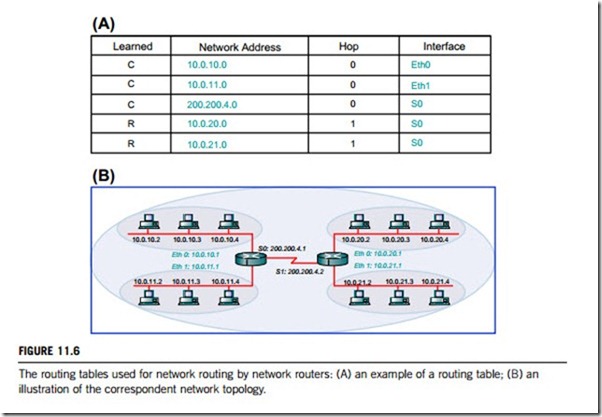
An example routing table is given in Figure 11.6. In part A, the first row of the table states that network 10.0.10.0 is on interface “Eth0” and the “C” in the “Learned” column means the information was learned through a direct connection; in other words, the network is local to the router. The last row states that network 10.0.21.0 is on interface “S0” and the “R” in the “Learned” column means the information was
learned through a routing protocol; in this case, the network is not local to the router. Figure 11.6(B) illustrates the network topology correspondent to the routing table given in Figure 11.6(A).
(3) Routing protocols
The routing protocol calculates the best path for forwarding data and ensures that routing information is sent regularly between routers, so that network information can be shared. This allows routers to build up information about network topologies and keep information about routes. The routing protocol also specifies how routers report changes and share information with the other routers in the network. It allows the network to dynamically adjust to changing conditions, which would be very difficult with static data.
Confusion often arises between the terms routing protocols and routable protocols. While routing protocols are used by the router to make the decision on which paths to send data packets, routable protocols are responsible for the actual transfer of data packets between network devices. Specifically, a routable protocol is any network protocol that provides enough information in its network layer address to allow a packet to be forwarded from one host to another, on the basic of an addressing scheme, without knowing the entire path from source to destination. Routable protocols define the format and use of the fields within a packet. Packets generally are conveyed from end system to end system.
The routing protocol on one system can be different from that used on another. A routing protocol used within an autonomous system is referred to as an internal gateway protocol (IGP); examples of which are RIP, IGRP, EIGRP, IS-IS and OSPF.
For routing between each autonomous system, an exterior gateway protocol (EGP), is required. The most common EGP in current use is Border Gateway Protocol (BGP). The Internet Assigned Numbers Authority (IANA), the body that regulates the assignment of IP addresses, allocates a unique 16-bit number to each autonomous system, known as the autonomous system number. BGP uses this information to route traffic between autonomous systems.
A number of routing protocols have been developed over the years. The more common of these are described below.
(a) Routing Information Protocol (RIP)
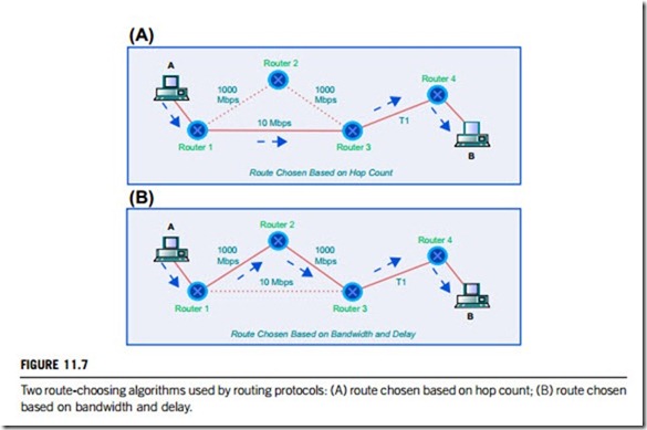
This is one of the most frequently used routing protocols on internal networks. RIP is a distance-vector routing protocol that uses a hop count as its routing metric. If there are multiple paths to a destination, RIP chooses the path with the lowest hop count which is not necessarily the fastest, as Figure 11.7(A) illustrates. RIP comes in different versions; RIP-1 and RIP-2. The later version was developed to overcome some limitations of the first. More information is contained inside an RIP-2 routing packet than an RIP-1 packet and a subnet mask field is included. Thus, RIP-2 can support classless routing and hence a network divided into subnets with different subnet masks.
(b) Interior Gateway Routing Protocol (IGRP)
This is a proprietary routing protocol developed for overcoming the RIP’s use of hop count as the routing metric and the hop count limit of 15 that made it unsuitable for use on larger networks. The maximum hop count of IGRP is 255, and like RIP, IGRP is a distance-vector routing protocol but it uses a more complex routing metric to determine path costs. Factors such as delay, bandwidth, hop count and reliability can be used in determining the fastest path, although delay and bandwidth are used by default. Figure 11.7(B) illustrates how the more complex metric of bandwidth and delay enables a superior path to be selected, compared to selection based solely on hop count.
(c) Extended Interior Gateway Routing Protocol (EIGRP)
This is also a distance-vector routing protocol, but is much more sophisticated than IGRP or RIP. To calculate the path costs, EIGRP uses a 32-bit metric which combines an assessment of the link bandwidth and delay. Routes are calculated more efficiently using an algorithm called the diffusing update algorithm. EIGRP has a higher rate of route convergence; in other words, routers exchange information and agree on routes more quickly. It will also query neighboring routers for information only when needed, so reducing the amount of traffic generated between routers. Unlike its predecessor, EIGRP is able to deal with classless routing, allowing the use of VLSM (variable length subnet masking).
(d) Open Shortest Path First (OSPF)
This is a protocol designed for large networks where protocols such as RIP may be unsuitable. It is a link-state routing protocol with an advanced metric algorithm; basing path selection on cost rather than hop count and without the limit of 15 hops in a route, hence allowing a network to grow beyond what RIP could support. With OSPF, a large network can be separated into smaller areas, confining
many of the routing processes to each individual area, but allowing routers to communicate between areas. This cuts down on network traffic since a router does not have to recalculate its routing table unless a route in its own area changes. The separation of a network into areas is called hierarchical routing. In general, OSPF provides faster route convergence and generates less traffic between routers than RIP or IGRP.
(e) Intermediate System to Intermediate System (IS-IS)
This is a protocol developed as part of the OSI protocol stack, and is used to manage routing within Connectionless Network Protocol (CLNP) networks. Integrated IS-IS is a derivation of the original IS-IS which was developed to support the IP protocol. As a link-state routing protocol, IS-IS has the same basic features as OSPF, including link-state advertisement, where link-state information is sent out across the network, allowing routers to maintain a current network topology. Variable-length subnet masking (VLSM) is also supported by IS-IS.
(f) Border Gateway Protocol (BGP)
This is an example of an exterior gateway protocol (EGP), allowing routing information to be exchanged between autonomous systems. Autonomous systems are independent networks controlled by different organizations, each running an interior gateway protocol of their choice. For routing between each of these systems, another routing protocol, an exterior gateway protocol, is required.
(4) Routing algorithms
There are two terms, static routing and dynamic routing, which should be introduced here.
(a) Static routing
This is simply the process of manually entering routes into the routing table to be loaded when the routing device starts up. Since they do not change after they are configured, these routes are called static routes. This is the simplest form of routing, but it is a manual process and does not work well when information has to be changed frequently, or needs to be configured on a large number of routing devices (routers). Static routing also does not handle outages or down connections well, because any route that is configured manually must also be reconfigured manually to fix any lost connectivity.
(b) Dynamic routing
These protocols are software applications that dynamically discover network destinations and how to reach to them. A router will “learn” routes to all directly connected networks first. It will then learn routes from other routers that run the same routing protocol. It will then sort through its list of routes and select one or more “best” routes for each network destination it knows or has learned. Dynamic protocols will then distribute this information to other routers running the same routing protocol, thereby extending the information on what networks exist and can be reached. This gives dynamic routing protocols the ability to adapt to logical network topology changes, equipment failures or network outages on the fly.
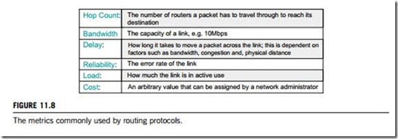
Every routing protocol uses an algorithm to calculate the best path to a destination, and each routing algorithm uses metrics to calculate path costs. Metrics are simply values, such as hop count, bandwidth, delay, reliability and load. These ones used depend on the routing protocol, for example, RIP uses the hop count metric only, but IGRP uses bandwidth and delay by default. The metrics most commonly used by routing protocols are shown in Figure 11.8.
Each routing protocol will probably be categorized as either a distance-vector or link-state, which refers to the complexity of metrics used, and the regularity with which routers send routing table updates to their neighbors.
(a) The distance-vector routing approach. This uses the distance to a link in a network as its routing
metric. Distance can be hops or a combination of parameters calculated to represent a distance value; the further the distance, the higher the overall metric cost. Examples of distance-vector routing
protocols and the metrics each one uses are: RIP v1 (metric: hops used); RIP v2 (metric: hops used); IGRP (metric: bandwidth and delay used). Whatever metrics are used to calculate distance, the path with the lowest cost is chosen as the best option. If hop count is used as the metric, then a path cost is the number of hops (routers) to the destination. All hops are seen as equal, regardless of their speed. Routes with the lowest hop count are preferred. Figure 11.9 gives an illustration of the distance-vector routing approach.
(b) The link-state routing approach. This also favors paths with the lowest cost within a network.
Link-state routers have link information passed to them from neighbors; they then pass that information on, to other neighbors. Eventually, all the routers have information about all the links on the network and build a kind of topological map of the network. Link-state uses the shortest-path-first algorithm to calculate the best path to a destination. OSPF is an example of link-state routing protocol. However, whereas distance-vector periodically broadcasts its routing table to its neighbors, link-state only broadcasts every 30 minutes or so, or when the state of a link changes. If a link changes from up to down or vice versa, a notification called a link-state advertisement is flooded throughout the network. All the routers note the change, and recompute their routes accordingly. A router therefore passes information to the whole network, telling them about its neighboring links only. Link-state routing generates less network traffic, responds more quickly to changes in network topology and offers faster route convergence than distance-vector routing.
(c) Variable length subnet masking (VSLM). This is the extension of the standard IP class subnetwork masks to include subnetworks. A routing protocol categorized as classical does not send subnetwork mask information with route updates. This means that only the standard IP class network addresses are recognized and understood. A network containing subnetworks would encounter problems if such a protocol was used. A classless routing protocol sends subnet information with any routing information, which means that router can recognize subnetworks within a network.
