The multispeed multiwinding motor is usually constant torque or constant horsepower. The speed ratio for each winding is 2 to 1. Several of these windings are combined in some multispeed drill press motors.
If a multispeed motor has more than one winding, the higher-speed winding will have higher lead numbers. For example, the lowest speed will have numbers Tl through T7, the higher speed T Il through T17, and T21 through T27 on the next-higher speed winding.
Two-Speed Two-Winding Motor
A two-speed motor with a speed ratio that isn’t 2 to 1 —for example, 1200 RPM/ 1800 RPM—will usually have two single-speed windings. The lead numbers are T1, T2, and T3 for the low speed and T11, T 12, and T13 for the high speed.
There’s no internal connection between them, and they should be tested as two different motors.
If one or both windings are delta connected, the internal connection
(described in Chapter 7, Fig. 7.4 under “Circulating Current in Multiwinding Multispeed Motors”) must be used. A rewound motor draws excessively high amperes if this connection isn’t used.
Multimode Nine-Lead Three-Phase Motors
Multimode motors are primarily used on oil well pumps. They must have high-slip rotors because of the uneven torque demand unique to oil well pumps. They also have special internal connections that are unlike those in any standard three-phase motor.
The external connections of the multimode motor are switched (by a control) to change the motor’s torque without changing its speed. The control changes the motor’s torque automatically when it senses a prolonged load change. The lower-torque mode reduces the amount of power consumed by the motor.
These motors are powered by either generators or long power lines, and they operate in remote locations. Both power sources benefit from having amperes as low as possible.
The multimode motor could be used on commercial air compressors. A commercial air compressor intermittently operates unloaded. During this time the standard motor consumes power and has a lower power factor. Replacing the standard motor with a multimode motor will reduce power cost while maintaining a good power factor during the unloaded part of the cycle.
TWO types of multimode designs are covered in this section: the triplemode design and the quadruple-mode design.
Comparing Multimode Motors to Standard Motors
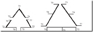
Multimode motors have nine leads. Like the dual-voltage nine-lead delta connection, they have three sets of three-lead circuits. Unlike the delta connection, each three-lead circuit contains a complete phase (Fig. 5.35).
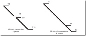
The 12-lead motor and the multimode motor both have leads that access both ends of each phase. Comparing the two in Fig. 5.36, the multimode motor’s A phase has T7 located at the end of the phase instead of T 10. The A phase of the multimode motor is an unbroken circuit with T4 located somewhere between Tl and T7 (depending on the number of torque modes).
FIGURE 5.35 Comparison of the nine-lead delta schematic with a nine-lead multimode schematic
FIGURE 5.36 Comparing the A phase of a 12-lead motor to the A phase of a multimode motor.
Triple-Mode, Nine-Lead Three-Phase Motor
The triple-mode motor has a lead at the center of each phase. Its data are equal from the center lead to each end of the phase.
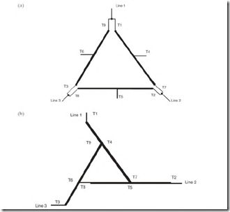
Figure 5.37 shows the connections for high, medium, and low torque. The delta connection (Fig. 5.37a) has the highest torque. Figure 5.37b is the wye-delta connection for medium torque, and Fig. 5.37c is the wye connection for low torque.
FIGURE 5.38 (continued) (c) The quadruple-mode motor connected wye-delta will have medium-low torque. (d) The quadruple-mode motor connected wye will have the lowest torque.
Figure 5.38a shows the delta connection, which has the highest torque.
Figure 5.38b shows the delta-wye connection with medium torque. Figure 5.38c shows the wye-delta connection with medium-low torque. Figure 5.38d shows the wye connection, which has the lowest torque.
Identifying the Quadruple-Mode, Nine-Lead Three-Phase Motor
The same identification logic is used on this motor as described above for the triple-mode motor. The quadruple-mode motor’s connection, however, is slightly different from that of the triple-mode motor.
This connection can be identified with an ohmmeter of the right size. There are three sets of three leads that light to each other. A-phase leads Tl to T4 have much less resistance than T4 to T7. The same is true of T2 to T5, T5 to T8, T3 to T6, and T6 to T9.


