Wireless Microphones
Modern wireless microphones allowing untethered motion of the user have proven themselves to be indispensable in concerts, religious services, dramatic arts, and motion picture or video production.
Wireless microphones for use in the performing arts and sound reinforcement first made their appearance about 1960. The first transmitter units were designed to operate in the broadcast FM band between 88 and 108 MHz. The receivers were conventional FM broadcast units. The transmitters did not have to be licensed as the low radiated powers involved complied with Part 15 of the FCC rules. Frequency modulation was accomplished in the transmitter by allowing the audio voltage signal to vary the junction
capacitance of a bipolar transistor connected as a Hartley or other simple oscillator tuned to the desired carrier frequency in the FM band.
Such oscillators were prone to drift in operating frequency as the transistor characteristics were sensitive to both temperature and supply voltage variations. This required periodic retuning of the receiver to compensate for transmitter frequency drift. This was particularly true of the very early units that employed germanium transistors. Significant improvement in this regard was made possible with the availability of suitable silicon transistors.
One of the authors well remembers hand crafting several body pack transmitters in 1965 for use by lecturers at Georgia Tech. The receivers employed were H. H. Scott units that had been modified to incorporate automatic frequency control circuitry to compensate for the transmitter drift within reasonable limits. These early units had acceptable audio bandwidths but the simple modulation technique employed did not produce large frequency deviations, resulting in a small dynamic range of the recovered audio signal.
Those of us who have experienced the entire history of wireless microphones consider the present-day versions to be truly remarkable. Not only have the early shortcomings been addressed but also features not even envisioned by the early practitioners have been added. Frequency space has been made available in both the VHF and UHF frequency bands with UHF units currently being more popular. The UHF band offers more flexibility with regard to the number of different frequencies that may be employed simultaneously as well as a higher probability of finding unused frequency space in a given locale. Additionally, required receiving antenna lengths are much more manageable in the UHF band. For example, with a carrier frequency of 900 MHz and a wave speed of 3 X 10⁸ m/s, the wavelength becomes one-third of a meter or about 13 inches. The required receiving antennas range between ¼ and ½ wavelength and thus have lengths falling between about 3 and 6 inches.
There are several significant technical innovations incorporated in current wireless microphone systems that are worthy of note. Each of these will be discussed in turn.
1. Receiver assisted setup.
2. Space diversity reception.
3. Transmitter preemphasis—receiver deemphasis.
4. Transmitter compression—receiver expansion.
A difficult problem associated with setting up wireless microphone systems in the past has been that associated with determining interference-free operating frequencies. This was particularly true when the application required the simultaneous operation of a large number of separate audio channels, each of which required an individual radio frequency assignment. Receivers having assisted setup facilities have built in protocols for scanning the entire operating band and identifying those potential operating frequencies that are free of any radio frequency carrier at the time of scan. Several such scans performed over a period of time usually are quite successful in defining interference-free operating frequencies.
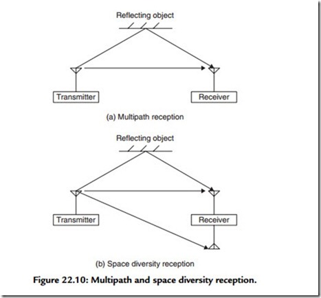
Space diversity reception solves a problem depicted in Figure 22.10(a) by means of an arrangement suggested by Figure 22.10(b).
In Figure 22.10(a), a single receiving antenna is employed. This antenna receives a signal via a direct path to the transmitter as well as a transmitter signal that has been reflected by a nearby object and thus follows a longer more indirect path along its way to the receiving antenna. The phases of these two signals having the same frequency are different and hence they can interfere with each other. The interference may be
either constructive or destructive according to the degree of phase difference. When the interference is destructive, the resultant signal may be so weak that the receiver will not be able to recover the program material.
The arrangement shown in Figure 22.10(b) greatly reduces the probability that there will be a complete loss of program material. In this arrangement, two antennas located somewhat less than a wavelength apart are employed. In this arrangement, the reflected
signal may not even arrive at the second antenna as shown. Even when this is not the case or when there are other reflecting objects, the chances that both antennas are subjected to destructive interference simultaneously are reduced greatly.
There are several techniques for handling the signals that appear in the space diversity antennas. In one technique the space diversity receiver is fitted with separate radio frequency amplifiers for each antenna. The signals from each of these amplifiers are compared as to strength with the stronger signal at any instant being switched to the remainder of the single receiver circuitry.
In a variation on this technique, the signals from both radio frequency amplifiers are summed and then fed to the rest of the circuitry of a single receiver with no switching being involved. Finally, two receivers set to receive the same carrier frequency are employed, one for each receiving antenna. The automatic gain control voltages that are developed at each receiver’s detection stage are compared with the audio output circuitry being switched to that of the receiver having the larger control voltage. This last technique is the most expensive and, even though it involves switching, has perhaps the best performance overall.
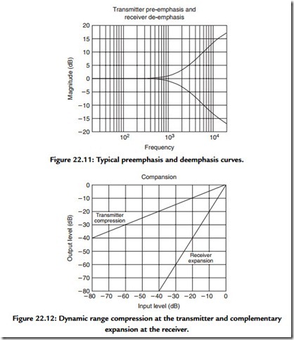
Wireless microphone transmitters employ a relatively small frequency deviation in the frequency modulation process. The modulation index is thus small. This restricts the dynamic range that is available for program material and weak signals may be lost in the noise floor. A long-term average of the spectral density associated with both voice and music programs exhibits a broad maximum in the vicinity of 500 Hz accompanied by a roll off in density beyond about 2 kHz. The spectral density is the average power per unit frequency interval. This being the case, it is necessary to pre emphasize the higher frequencies in the audio material prior to further signal processing.
The normal range of the audio material to be transmitted may well be as large as 80 dB while the available range in the small deviation FM transmitter may be only 40 dB. The 80-dB range of the audio material is squeezed into the 40-dB range available by 2 into 1 compression prior to the modulation process. After transmission and reception at the receiver, the recovered audio material occupying a 40-dB range is first subjected to a 1 into 2 expansion in order to restore the full dynamic range of 80 dB.
This is then followed by a de emphasis of the audio material above 2 kHz in order to restore the natural spectral balance of the audio material. Figure 22.11 displays typical preemphasis and complementary deemphasis curves with the upper curve being that of preemphasis. The combination of the two yields a flat response across the audio band.
The process of compressing the audio dynamic range prior to transmission and expanding the range of the audio material following reception has been termed compansion. A typical compression curve employed in the audio circuitry of the transmitter, followed by the complementary expansion curve employed in the audio circuitry of the receiver, is displayed in Figure 22.12.
Transmitter pre-emphasis and receiver de-emphasis
Transmitter units may be hand-held with a built-in microphone element or a body pack unit provided with a minireceptacle for a microphone connection. The microphones employed with body pack units are usually miniature dynamic or electret capacitor microphones attached to short cables fitted with mating connectors to that of the transmitter.
The microphone elements are fitted with clips for attachment to the user’s clothing. Occasionally, the microphone element may be part of a head microphone boom structure.
Typical transmitter features are:
1. Power on–off switch.
2. Carrier frequency selection and indicator.
3. Battery level indicator.
4. Audio gain control.
5. Audio overload indicator.
6. Audio mute switch on body pack units.
7. Nine-volt battery.
Receiver units may be stand-alone or rack mounted and are usually powered from conventional power mains. Audio outputs are provided at both line and microphone levels.
A typical space diversity receiver providing assisted setup has the following features:
1. Power on–off switch.
2. Scan or operate control.
3. Carrier frequency indicator.
4. Squelch control.
5. Active receive antenna indicator.
6. Radio frequency level indicator.
7. Transmitted audio level indicator.
8. Transmitter battery life indicator.
9. Audio output level control.
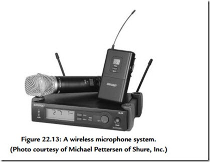
A photograph of a space diversity wireless microphone system is presented in Figure 22.13.
One final note with regard to wireless microphone systems distilled from years of sad personal experience. The first three rules for dealing with wireless microphone systems are:
1. Batteries.
2. Batteries.
3. Batteries!
Wireless transmitters are usually powered by 9-V batteries that may be composed from primary or nonrechargeable cells or secondary cells that are rechargeable. Even if one ordinarily uses rechargeable batteries, it is well to keep a fresh supply of nonrechargeable units on hand. The histories of rechargeable batteries must be managed carefully in order to assure their proper performance. Many practitioners prefer to employ only fresh nonrechargeable batteries along with frequent replacement because of sad experiences with rechargeable units. Battery failure at a critical moment can lead to years of bad dreams.
