THERMOCOUPLE-TYPE METERS
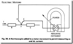
This type of instrument employs one or more thermojunctions (ther mocouples) which, when heated directly or indirectly by an electric current, generate an electric current. When this generated current is made to flow through a permanent-magnet, moving-coil, such as in Fig. 30, a deflection proportional to the difference in temperature of the junctions takes place.
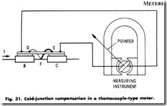
The voltage from a thermocouple is proportional to the difference in temperature between the heated junction and the point at which the thermocouple wires are connected to the copper leads of the instrument. Therefore, any change in the temperature of this latter connection point will result in an error in instrument indication. To avoid errors caused by this condition, it is common practice to terminate the heater in rather massive blocks, and then bring the point at which the thermocouple leads join the copper circuit into good thermal contact with these blocks. This is usually done by connecting the leads to a thin copper plate, and separating them from the block by a thin mica strip. This is called cold-junction compensation (see Fig. 31) and serves to maintain the connection to a fixed relation to the temperature of the heater.
The meters used with thermocouples to measure current must neces sarily be more sensitive than those used with shunts, because the emf developed by a thermocouple is quite small. For example, such a thermocouple may have an output voltage of only 15 millivolts, and an internal resistance of 5 ohms. This means that thermocouple instru ments should be carefully handled, since the construction is necessarily somewhat delicate.
HOT-WIRE TYPE METERS
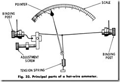
This type of instrument depends on the heat expansion of a wire carrying a current for its operation. With reference to Fig. 32, the instrument functions as follows: The current being measured causes a wire, through which the current flows, to heat up and thus expand or increase in length approximately in proportion to the square of the current flowing (12). The change in the length or the sag of the wire is amplified and arranged to drive the pointer.
Instruments of this type are made in different forms with various arrangements of their wires and parts. All of them, however, work on the same principle. Because this instrument functions as a result of the heating effect of the current, it can be used for measurements on both de and ac circuits. This instrument is not employed where great accuracy is desired. This is mainly due to the instability of the wire stretch and the lack of ambient-temperature compensation. It is now being largely replaced by the more sensitive, more accurate, and better compensated permanent-magnet, moving-coil combinations previously described.
METER CONNECTIONS
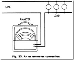
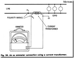
The current in an electric circuit is measured by the ammeter. Always connect an ammeter in series with the load (Fig. 33) whose current it is desired to measure–never across it. When a current transformer is used, always ground its secondary, as shown in Fig. 34.
Measurement of Alternating Current
If an ammeter is to be used on circuits of devices that have a high starting current, such as motors, short out the ammeter until after the starting period. Or, if the meter is to be left in circuit for some time, use a short-circuiting switch to avoid damaging the instrument. The switch can be opened at any time when a reading is to be taken.
Measurement of Direct Current
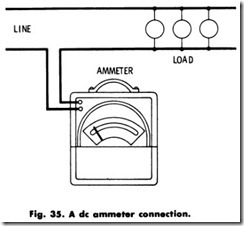
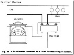
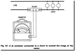
If one side of the line is grounded, ammeters should be connected to that side. External and internal shunts are used for measurements of large current values. If the instrument reads backward, reverse the meter leads. Various de ammeter connections are shown in Figs. 35, 36, and 37.
Measurement of AC Voltage
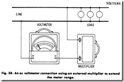
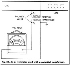
The potential or voltage across a circuit is measured with a voltmeter. Always connect a voltmeter across the load whose voltage it is desired to measure–never in series. To extend the range of a voltmeter, a multiplier may be used. If a higher rated voltmeter is not available use a potential transformer. Always ground the potential-transformer secon dary. Typical voltmeter connections are shown in Figs. 38 and 39.
