INDUCTIVE- TYPE CONTACTORS
Inductive-type contactors are similar in appearance to the previously described double-coil contactor. The differ only with respect to the arrangement of the lockout magnet, which is constructed of heavy iron.
In operation, the relative strength of the main closing and holdout coils are so adjus ted that the contactor will remain open, with full voltage on the main closing coil and approximately one percent of the operating voltage on the holdout coil. When the magnetic contractor is operated by pressing the START button, both coils are energized simultaneously and the holdout coil is short-circuited. The magnetic circuit comprising the holdout coil is constructed so that a certain time interval is required for the residual flux to decrease to a value permitting the contactor to close its circuit. This time interval is adjusted by changing the length of an air gap in the holdout magnetic circuit.
CONTACTOR RATINGS
The rating of a pair of current-carrying contacts is generally ex pressed in terms of make, break, and carry.
Make is defined as that value of transient or steady current which the contacts can establish without welding. The current which a set of tips can make is not constant, but depends to a considerable degree on the design of the device on which the tips are used. Some sparking may be visible at the moment of make because of certain irregularities in the tip surface, and because of the relative motion of the tips as they travel from their first contact point to their final position.
The statement that a device will break a certain current means that it is capable of interrupting the flow of that amount of current without excessive arcing or burning.
The Underwriter’s Laboratories specify:
1. That a contactor rated in amperes shall be tested for durability by interrupting it at its rated current 6000 times at intervals of 1 second.
2. That it shall be able to interrupt 150% rated current 50 times at intervals of 10 seconds.
It is further specified that de devices shall be tested with a non-in ductive resistance load, while ac devices shall be tested with an inductive load.
The term carry designates the load current that can be continuously conducted without excessive temperature rise. The Underwriters’ La boratories specify that, with a motor load, the contacts shall carry 115% of their ampere rating continuously until their temperatures are constant without exceeding a 167° F (75° C) rise, and that the contacts shall carry 100% of their rating and meet these conditions on all other loads.
The eight-hour rating given devices was agreed upon by the industry in recognition of the fact that most standard devices cannot be energized continuously for days without exceeding a safe temperature rise. It requires the periodic cleaning action of both the arcing and the physical opening and closing of the contacts to remove the high-resistance oxides which would otherwise form.
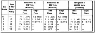
The NEMA standard eight-hour open rating for ac contactors shall be 15, 25, 50, 100, 150, 300, and 600 amperes.
The open eight-hour rating for de contactors shall be 25, 50, 100, 150, 300, and 600 amperes.
The eight-hour open rating for ac and de contactors rated more than 600 amperes has been suggested as 1200 and 2400 amperes.
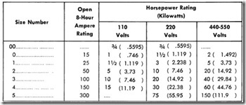
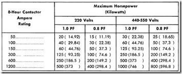
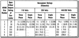
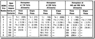
The ratings for various ac and de contactors are given in Tables 1 through 13.
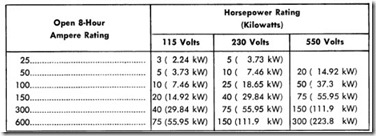
Table 1. Contactor Ratings for Line, Reversing, and Final Ac celerating for General-Purpose and Machine-Tool DC Magnetic Starters
Intermediate accelerating contactors shall be selected so that the open eight hour ampere rating shall not be less than one-quarter the maximum current for that step.
Table 2. Contactor Ratings for Continuous-Duty Steel Mill Auxiliary Standard DC Accelerating Contactors
Table 3. Contactor Ratings for Mill Duty Accelerating Contactors
*As specified by the user.
The minimum contactor rating to be offered as standard with control for de steel mill auxiliaries shall be the 100-ampere eight-hour rating.
MAINTENANCE
Proper maintenance of contactors plays a very important role in their satisfactory functioning and will increase their life span and the econ omy of their operation. One important factor to remember is that the use of lubricants on the contacts or bearings should be avoided. Oil quickly collects dust and, unless the parts are frequently cleaned, will interfere with the operation of the contactor. Oily surfaces that collect dust may also result in an arc between live parts of the contactor.
Most contactors are furnished with flexible braided-copper shunts which are designed to give complete freedom to the moving armature with sufficient current-carrying capacity. Burned or badly corroded shunts should be promptly replaced.
Range of Operating Voltage Contactors generally are designed to operate properly if the line voltage is within 85 to 110 percent of the nameplate rating for ac circuits, and within 80 to 110 percent for de circuits. Wider ranges usually require special devices.
Where there is a continuous 10 percent increase in voltage, suitable coils should be ordered because, with this increase in voltage, there is approximately a 50 percent increase in wattage. The latter greatly increases the heating of the coil, causes a rapid deterioration of the
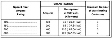
Table 4. Contactor Ratings for Crane Standard DC Contactors
Note 1-General-purpose control will be considered as suitable for steel-mill accessory machines.
Note 2-The minimum contactor rating to be offered as standard with crane control shall be the 100 ampere, 8-hour rating.
Note 3-Accelerating contactors shall be the same rating as the line contactors and shall be equipped with blowouts.
Note 4-The number of accelerating contactors is exclusive of the plugging contactor.
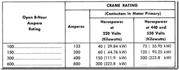
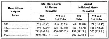
Table 5. Contactor Ratings for DC Crane Protective Panels
Note 1-For motors of other voltage ratings, the 8-hour rating of the mam line contactor shall not be less than 50% of the combined one-half or one-hour rating of the motors, nor less than 75 o of the one-half or one-hour rating of the largest individual motor.
Note 2-ln no case shall the main line contactor of the protective panel be of smaller rating than the largest contactor used on any of the controllers protected
Table 6. Contactor Ratings for AC Crane and Hoist Duty
Note 1-The minimum contactor rating to be offered as standard with ac crane control shall be the 100 ampere, 8-hour rating.
Note 2-Accelerating contactors shall be equipped with blowouts, and shall have a crane rating of not less than the full-load secondary current of the motor.
Note 3-When used for motor secondary control, the ampere rating of a three pole ac contactor with its poles connected in delta, sha II be 1.5 times it standard crane rating.
Note 4-The number of accelerating contactors is exclusive of the plugging con tactor for reversing controllers and the low-torque contactor for hoist controllers.
Table 7. Number of Accelerating Contactors for AC Crane and Hoist Duty
insulation, and shortens the ultimate life of the coil. There is also an approximate increase of 20 percent in the pounding effect, resulting in a more rapid deformation of the armature, crystalization of the magnet parts, breaking of the contact tips, and an increase in noise.
Contact Movement
The armatures should seal when the proper voltage is applied to the coils, and should open by gravity when the power is cut off. All contacts should, when closed, make line contact near the bottom of the face. On opening, the final break should be at the top. The rolling and wiping motions when closing and opening keep the contacts in good condition by removing any oxidation that might tend to accumulate on their faces.
Interlock Adiustment
Electrical interlocks are usually factory adjusted to make contact at approximately the same time that the main-contactor tips touch, or even a trifle later. However, for some special applications, the interlocks may make contact before the main tips touch. To change this adjustment, the usual procedure is to loosen the nuts on the front and back of the base, and to screw the stud in and out to suit the conditions.
Mechanical interlocks are usually so adjusted that, with one contactor in the sealed closed position, there is a very little play on the other
Table 8. Contactor Ratings for AC Crane Protective Panels
Note 1-For motors of other voltage ratings, the 8-hour rating of the main line contactor shall not be less than 50o/o of the combined one-half or one-hour rating of the motors, nor less than 75o/o of the one-ha If or one-hour rating of the largest individual motor.
Note 2-ln no case shall the main contactor of the protective panel be of smaller rating than the largest primary contactor used on any of the controllers protected thereby.
contactor . This play must not be great enough to permit the moving contacts of the second contactor to touch the corresponding stationary tips when the tips of the first contactor are just touching.
Table 9. Contactor Ratings for Polyphase Multispeed Motors
Note 1-For constant hp (2, 3, and 4 speeds).
Note 2-For constant and variable torque motors (2, 3, and 4 speeds), the horse power ratings shall be the ratings standard for across-the-line starters shown in Table 12.
Table 10. Ratings of AC Low-Voltage Contactors used with Synchronous Motors, Starters, and Controllers
Note 1-The accelerating contactor of single-step primary-resistor, autotransform er, and reactor starters shall have the same rating as the line contactor when the line contactor has an 8-hour rating of 150 amperes or less. When the line contactor has an 8-hour rating of 300 amperes or larger, an accelerating contactor having the next lower rating may be used.
Note 2-The accelerating contactors if multiple-step starters shall have the same rating as multiple-step ac starters.
Contact Pressure
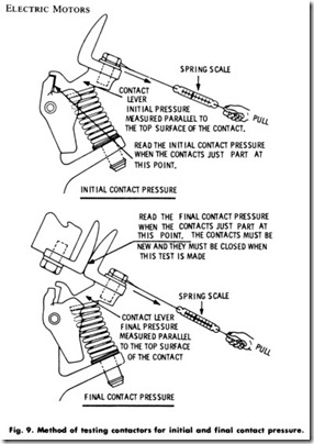
Contactors for various classes of service are designed with a definite contact -spring pressure. To avoid undue heating of the contacts, it is important that this spring pressure be maintained at a constant rate. The pressure can be checked with a properly calibrated spring balance, as shown in Fig. 9.
Contact Heating
A contactor has several bolted and spring-closed contacts. Exces sively high resistance at these contacts can be the cause of very high temperatures (100 to 200°C) (212°F to 392°F) when the contactor is
Table 11. Ratings of AC Reduced-Voltage General-Purpose Magnetic Starters
Note 1-The single-phase ratings apply to either two- or three-pole contactors. Note 2-The standard horsepower rating adopted for three-phase starters shall apply to two-phase, four-wire and two-phase, three-wire starters. A current rating of 90°/o of the 8-hour rating of the contactor employed sha II apply, based on the average of the currents in the three legs of the two-phase circuit.
Note 3-The accelerating contactor of single-step, primary-resistor, autotransform er, and reactor starters, shall have the same rating as the line contactor when the line contactor has an 8-hour rating of 150 amperes or less. When the line con tactor has an 8-hour rating of 300 amperes or larger, an accelerating contactor having the next lower rating may be used. The accelerating contactors of multiple step starters shall have the same rating as for network starters.
Note 4-The intermediate accelerating contactors of secondary-resistor starters shall be selected so that the 8-hour open rating will not be less than one-sixth of the accelerating peak current. The 8-hour open rating of three-pole, delta-connected secondary contactors is 150% of the normal star-connected rating.
carrying less than the rated current. The most likely point of high resistance is at the contacts where the movable tips meet the stationary tips.
High resistance, however, may occur at any of the several bolted joints of the contactor. Therefore, if any of these devices begin to develop an excessive temperature, a millivoltmeter should be employed to ascertain which joints have a high voltage drop across them.
Table 12. Ratings of AC Across-the-Line Magnetically Operated Starters
Note 1-This table applies to all starting, reversing, and throw-over switches furnished with any type of enclosure, either with or without disconnecting means or other accessories. The enclosures may have operating shafts, pushbuttons in the case, reset rods passing through the case, slots for test jacks (with covers thereover) or similar openings which are filled by the shaft rod or other member passing through them.
Note 2-The single-phase ratings apply to either two- or three-pole starters.
Standard two-pole magnetic starters, reversing and nonreversing, for single-phase motors will have overload protection in one leg only.
Table 13. Ratings of AC Across-the-Line Manually Operated Starters
When copper contacts with a high resistance have been located, correction can be made by opening the contacts and removing the oxide film with a file (not with sandpaper or carborundum paper). It is unusual to find a high resistance in a bolted joint unless the contactor has previously reached excessive temperatures. When excessive resistances are found in joints, however, the cause should be removed.
Since high resistances will most commonly be found in the active contact, it is a very simple matter to inspect these tips weekly or monthly. If the temperature is unduly high, the tips should be lightly filed. The foregoing remarks apply particularly to copper contacts, because they oxidize readily and because the copper oxide thus formed has a very high resistance. A file will remove the oxide and again reduce the resistance to a low value.
Electrical interlocks may also fail because of the oxidation of copper contacts. Sometimes such failure occurs because of dirt between the contacts. Using one hemispherical and one flat tip made of silver will overcome both of these troubles. The face of the hemispherical unit will make contact without trapping foreign particles between it and the flat tip.
Excessive wear on contact tips of a contactor indicates that it is
operated frequently. Silver contacts should not be used for conditions of this kind, or where the current exceeds 25 amperes, because they do not stand up as well as copper under severe service. If the service is usually heavy, and if the current is equivalent to no more than three-fourths of the contactor’s rating, the tip can be faced with an alloy such as copper-tungsten that will last several times longer than copper.
Rough Contacts
Numerous maintenance men have the erroneous impression that contact tips which have been roughened by service should be kept smooth. A roughened tip will carry current just as well as a smooth tip. Of course a large projection on a tip, caused by unusual arcing, should be removed. However, a tip that has been roughened by ordinary arcing need not be serviced. If a copper tip becomes overheated, oxide will form and should be removed.
Contactor Coils
A large percentage of contactor-coil troubles are caused by over heating. Therefore, if the temperature can be reduced, coil troubles can be greatly minimized. Since the heating of a de coil will vary as the square of the voltage, and the heating of an ac coil will vary approxi mately as the cube, it follows that coils should be wound for the voltage that exists on the line. If the ambient temperature is high, this precau tion is all the more important.
When an ac magnet, such as a solenoid, is supplied with constant voltage excitation, a large inrush of current is required to close the armature. When the armature closes, the coil current drops to a normal value. Sometimes the armature may not close (because of excess friction or some other reason) and the resulting large in-rush current may burn out the coil within a few seconds. Such mishaps can be prevented by the use of a thermal cutout. When the thermal cutout opens because the armature fails to close, it is merely necessary to replace a small link made of two pieces of metal held together by a low-melting-point solder.
Some of the contributing causes of overheating of ac contactor coils are:
1. Overvoltage,
2. Low frequency,
3. Excessive magnetic gap caused by faulty assembly of the magnet parts, or an accumulation of dirt, rust, or paint on the pole faces,
4. Failure of the armature to close completely because of low voltage or mechanical interference,
5. Too frequent operation.
The current in ac shunt coils is at a minimum value when the armature seals properly with the stationary frame. Any gap in the magnetic circuit lowers the impedance of the coil, allowing the coil to draw more current. If the magnet is accidentally blocked open, or if the voltage is so low that the magnet cannot close, the current is likely to be several times greater than the minimum-gap current, and if this condi tion occurs, the coil may soon be damaged.
Unfortunately, the leads on coils are often used as carrying handles.
Although the leads are strong enough to support the weight of the coil, this practice should be discouraged. It is quite easy to completely or partially fracture the lead wire or joint, resulting in either an open-cir cuited coil or one that may open shortly after being installed.
If the coils become wet, it is advisable to bake them as soon as possible in an oven at a temperature of 110° to 125°C (230°F to 257°F). This should also be done if the coils have been soaked in carbon
tetrachloride or other degreaser to remove grease or oil. If necessary to paint the coils, only an approved insulating paint or varnish should be used. Some paints or varnishes contain thinners that will rapidly attack the insulation. Apply the paint while the coils are still warm from baking.
SUMMARY
A contactor is a device, operated other than by hand, for repeatedly establishing and interrupting an electric power circuit. Contactors are employed in control circuits and in power circuits, and as single units or in groups with load currents on the main contacts ranging from a fraction of an ampere to thousands of amperes, depending on the application.
Electrical interlocking generally consists of a system of wiring whereby, when one of the inter locked devices is operating, the control circuit to a second device cannot be completed; or the wiring may be such that the second device or starter cannot be energized until the first device or starter has been placed in operation. Mechanical interlocking consists of a mechanical arrangement whereby one of the interlocked devices is prevented mechanically from functioning when the other is energized; or, in some applications, where it is necessary to prevent closing of one contactor when a second contactor is closed.
The ac type of contactor produces a distinct hum or chattering pitched at twice the frequency of the circuit, whereas the de contactor is entirely noiseless. The chatter effect is usually reduced to a minimum in an ac contactor by means of a pole shader or shading coil.
Formerly, the principal method employed in contactor arc extinction in both ac and de circuits was the use of magnetic blowout coils. The arc is extinguished by a powerful blowout field and by stretching the arc across the splitters, thereby lengthening it until instability and extinction occur. The deion type of contactor has been designed to satisfy the demand for a contactor of increased interrupting and current capacity for use in small enclosures. The term is used to designate any type of arc-extinguishing apparatus which functions by rapidly restoring the insulating properties of air or gases in which it operates, by some means other than simply stretching or cooling the arc.
A shunt contactor is operated by a shunt coil energized from a constant-voltage power source. For de operation, these contactors are usually of the single- or double-pole type.
Lockout contactors are used principally as a means of obtaining current-limit acceleration on de motors. These contactors are con structed so that the contacts do not close until the current in the circuit has dropped below a definite value. The single-coil type is called a series condactor and the two-coil type is called a series lockout condactor.
The rating of current-carrying contacts is generally expressed in terms of make, break, and carry . The value of transient or steady current which the contacts can establish without welding is known as make. The statement that a device can break a certain current means that it can interrupt the flow of that amount of current without excessive arcing or burning. The term carry indicates the load current that can be conducted continuously without excessive temperature rise.
REVIEW QUESTIONS
1. Give the definition for a contactor.
2. What are the most common types of relays?
3. What is the purpose of the shading coil in an ac contactor?
4. What two methods are used to suppress the arc in electrical contactors?
5. What is the purpose of a lockout contactor?
6. How are magnetic contactors rated?
