Electrical Analogue
The analysis of mechanical and acoustical circuits is made very much easier by the application of analogues in which mass is equivalent to inductance, compliance to capacitance, and friction to resistance. Using SI units, direct conversion among acoustical, mechanical, and electrical elements can be performed.
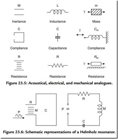
The three basic elements (RCL) of acoustical, electrical, and mechanical, systems are shown schematically in Figure 23.5. The inertance M of an acoustic system is represented by the mass of gas contained in a constriction that is short enough so that all particles are assumed to move in phase when actuated by a sound pressure. The compliance C of the system is represented by an enclosed volume, with its associated stiffness. It should be noted that the mechanical analogue of acoustic compliance is not mechanical stiffness, but rather its reciprocal, mechanical compliance Cm = Vs. Although resistance of an acoustic system may be due to a combination of a number of different factors, irrespective of its origin, it is conveniently represented by narrow slits in a pipe, for the viscous forces that arise when gas is forced to flow through these slits always results in the dissipation of energy.
The Helmholtz resonator may be graphically represented by Figure 23.6, but converting it to its electrical analogue shows it to be a simple resonant circuit, which can be analyzed easily using general circuit theorems.
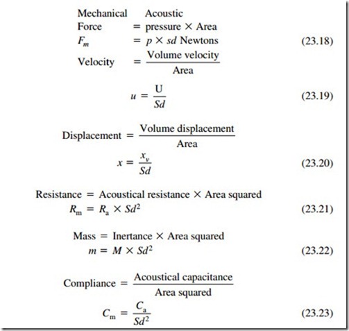
The beauty of the analogue method of analysis is that it is possible, by using various transformation equations, to refer the acoustic and electrical parameters to the mechanical side or, conversely, the mechanical and acoustic parameters to the electrical side, etc. For the purpose of this analysis the electrical and acoustical parameters are referred to the mechanical side. The diaphragm can be thought of as an acoustic/mechanical transducer, that is, a device for transforming acoustic energy to mechanical energy, and vice versa. Under these circumstances it will also act as an impedance transformer, that is, it will convert acoustic inertance into mechanical mass and acoustic compliance into mechanical compliance and acoustic resistance into mechanical resistance. The equivalent mechanical values of the acoustical quantities may be obtained from the following relationships:
Assuming that the diaphragm behaves as a rigid piston and is mass controlled, the power response is shown in Figure 23.7 where f0 is the system fundamental resonant frequency. Above this, the system is mass controlled and provides a level response up to ft; this corresponds to Ka = 2 (see Figure 23.3). Above this frequency the radiation resistance is independent of frequency, and the response would fall at 12 dB/octave, but because of the “directivity” effect, the sound field is concentrated into a progressively narrower beam. The maximum theoretical rate of rise due to this effect is 12 dB/octave, thus the on-axis HF response should be flat. In real life this is only approximated.

