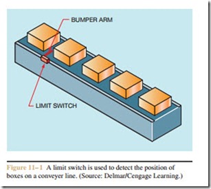
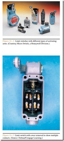
Limit switches are used to detect when an object is present or absent from a particular location. They can be activated by the motion of a machine or by the presence or absence of a particular object. Limit switches contain some type of bumper arm that is impacted by an object. The type of bumper arm used is determined by the application of the limit switch. When the bumper arm is impacted, it causes the contacts to change position. Figure 11–1 illustrates the use of a limit switch to detect the position of boxes on a conveyer line. This particular limit switch uses a long metal rod that is free to move in any direction when hit by an object. This type of bumper arm is generally called a wobble stick or wiggle stick. Limit switches with different types of bumper arm are shown in Figure 11–2.
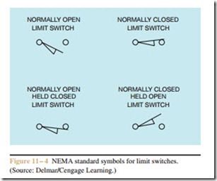
Limit switches vary in size and contact arrangement depending on the application. Some are constructed of heavy gauge metal and are intended to be struck by moving objects thousands of time. Others are small and designed to fit into constricted spaces. Some
contain a single set of contacts and others contain multiple contacts, as shown in Figure 11–3. Some limit switches are momentary contact (spring returned) and others are maintained contact.
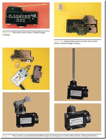
Generally, limit switches are used as pilot devices to control the coil of relays and motor starters in control circuits. The standard NEMA symbols used to indicate limit switches are shown in Figure 11–4. The wedge drawn under the switch symbol represents the bumper arm of the switch.
Micro Limit Switches
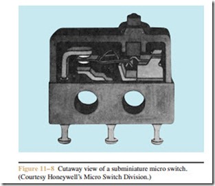
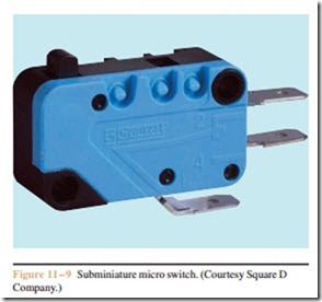
Another type of limit switch often used in different types of control circuits is the micro limit switch or micro switch. Micro switches are much smaller in size than the limit switch shown in Figure 11 – 3, which permits them to be used in small spaces that would never be accessible to the larger device. Another characteristic of the micro switch is that the actuating plunger requires only a small amount of travel to cause the contacts to change position. The micro switch shown in Figure 11 – 5 has an activating plunger located at the top of the switch. This switch requires that the plunger be depressed approximately 0.015 inch or 0.38 millimeters. Switching the contact position with this small amount of movement is accomplished by spring loading the contacts, as shown in Figure 11– 6. A small amount of movement against the spring will cause the movable contact to snap from one position to another.
Electrical ratings for the contacts of the basic micro switch are generally in the range of 250 volts AC and 10 to 15 amperes, depending on the type of switch. The basic micro switch can be obtained with a variety of different activating arms, as shown in Figure 11 – 7.
