Testing Lighting Circuits
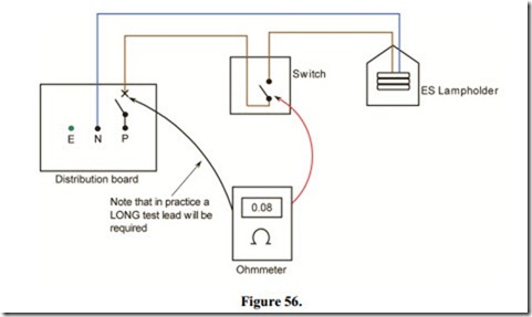
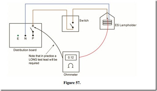
A “polarity test” must be done on all lighting circuits when new or after an alteration has been made. This is to ensure that the phase conductor is connected to the FUSE or MCB and single pole switches, rather than the neutral. See Figure 56. Any Edison Screw type lampholder should also be checked to ensure that the phase conductor is connected to the centre contact and the neutral to the screw contact,. See Figure 57.
This test must be done with the supply “DISCONNECTED” and may be carried out as follows:
· Remove circuit FUSE or open MCB.
· Remove all lamps from relevant circuit.
· Connect one lead of the ohmmeter to the phase conductor in the distribution board as shown.
A wander lead of known resistance is required to reach from the distribution board to each switch and lamp position.
· Connect the other lead to the switch feed terminal. See Figure 56.
A very low resistance value should be indicated, corresponding to the length and CSA of the conductor involved. This resistance should be indicated, regardless of the switch position,
· Move lead to the ES centre contact. See Figure 57.
A very low resistance value should be indicated, only when the switch is in the “on” position.
Note:
The circuit switch must be operated when checking polarity of ES lampholder.
If the continuity of the neutral conductor is also checked, we can say that the circuit will function correctly.

