Mini-trunking Systems
There is a wide variety of types and sizes of plastic mini-trunking manufactured today. One of the most common sizes of mini-trunking in use is 25mm wide and 16mm deep.
The following table illustrates the range of sizes available from one manufacturer. Sizes are quoted in millimetres.
Plastic mini-trunking is also available in sizes from 10 x 8mm to 38 x 25mm in self-fixing format. It has double-sided adhesive tape for ease of installation. The lid can easily be removed for maintenance or alteration of the wiring system.
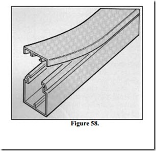
Figure 58 illustrates a section of 16 x 16mm mini-trunking, also shown is how the lid is fixed in place.
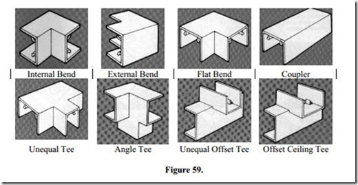
There is a wide range of snap-on mini-trunking fittings available. These allow for changes in trunking sizes and the direction of trunking runs.
Figure 59 illustrates a sample of the snap-on fittings available:-
Also available is a range of switch and socket boxes to suit the various trunking sizes.
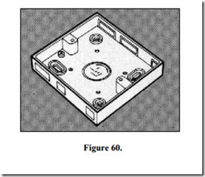
Figure 60 shows a single switch box, which is 19mm deep and has knockouts to cater for 16 x 16mm or 25 x 16mm trunking entering the top or bottom. The box may be fitted either way up to allow either size of trunking enter in the centre or towards the left or right hand corners. Note the slotted fixing holes, which facilitate accurate alignment.
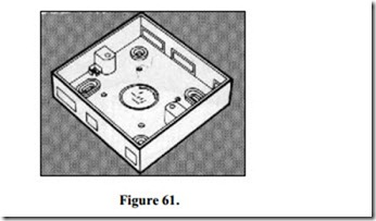
Figure 61 shows a single socket box, which is 25mm deep. Other box sizes are available to accept larger accessories or cables.
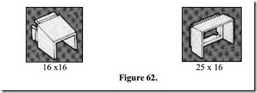
Figure 62 illustrates the adaptors used to terminate the plastic trunking into the type of box shown in Figures 60 and 61. This adaptor simply clicks into position on the box.
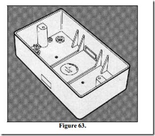
Figure 63 shows a double socket box, which is 32mm deep. This particular box allows for the direct entry of 25 x 16mm trunking to the centre, top or bottom. Side entry versions of all these boxes are also available.
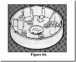
Figure 64 shows a ceiling rose adaptor. The adaptor allows for the entry of 16 x 16mm or 25 x 16mm trunking. It is designed to accept all popular makes of ceiling rose and batten lampholder.
Fixing Switch and Socket Boxes
· Select appropriate box and mark position.
· Select required knockout in box ( LH., RH, centre, top or bottom ), remove the knockout and then remove burrs from aperture.
· Snap in appropriate adaptor. This can more easily be done, by using a short length of trunking inserted in adaptor.
· Punch through the fixing holes in back of box and secure with screws.
· Insert the trunking into the box making sure that it seats securely in the adaptor.
Self-Fixing Mini-Trunking
To locate self-fixing mini-trunking, peel off the backing paper exposing 500mm of self adhesive tape at a time. Line up the trunking accurately and press home. The self-adhesive tape will bond to almost any dust-free surface. Surfaces must be smooth and flat. Uneven surface contact will reduce the bonding performance of the self-adhesive tape. Surfaces must be clean and dry. Installation of trunking in cold conditions may affect adhesion. Wood, plaster, plastics, metals, brick, paintwork, paper and glass are suitable surfaces.
Fixing Mini-Trunking
The fixing technique used will vary depending on whether the joints are mitred or moulded fittings are used.
Mitred Joints:
1. Plan the route of the main trunking run together with tees, drops to switches and socket outlets etc. Mark the positions and fix all boxes.
2. The trunking must be accurately mitred for bends and tees etc. Cut the trunking body and lid in the one operation. Where frequent temperature changes are likely, allow for expansion of approximately 0.7mm per 10°C per metre. Fix the body of the trunking by drilling oversized holes and screwing through the base with roundhead screws. Do not over tighten the fixing screws. The oversized holes allow for movement due to expansion. It is recommended that for installations at low level, fixing centres should be no greater than 375mm. For high level installations fixing centres should be no greater than 600mm.
3. Cables are now installed. Clip on the lid, making sure that the lid and base joints are staggered for better security. Ensure that the lid is clipped on properly throughout its length.
Moulded Fittings:
1. Plan the route of the main trunking run together with tees, drops to switches and socket outlets etc. Mark the positions and fix all boxes.
2. Where moulded fittings are used the need for accurate mitring is eliminated. The trunking ends need only be cut to butt each other. Where frequent temperature changes are likely, allow for expansion of approximately 0.7mm per 10°C per metre. Fix the body of the trunking by drilling oversized holes and screwing through the base with roundhead screws. Do not over tighten the fixing screws. The oversized holes allow for movement due to expansion. It is recommended that for installations at low level, fixing centres should be no greater than 375mm. For high level installations fixing centres should be no greater than 600mm.
3. Cables are now installed. Clip on the lid by sliding one end under the cover of the first moulded fitting. Mark the lid about 6mm beyond the next fitting and cut. Spring the end of the lid under next fitting and snap it into position along the main body of the trunking. Repeat this procedure between fittings until installation is complete.
Mini-Trunking Fitting
Coupler
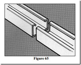
Cut the trunking to length as required. Allowing an appropriate gap for expansion, butt the ends together, as shown in Figure 65.
Tee
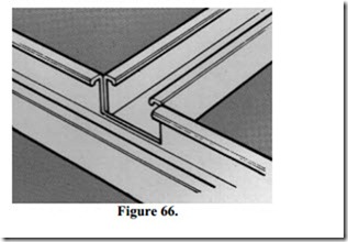
Cut the trunking to length as required. Remove a section of the sidewall of the through trunking. Allowing an appropriate gap for expansion, butt the tee trunking to the opening, as shown in Figure 66.
Flat Bend
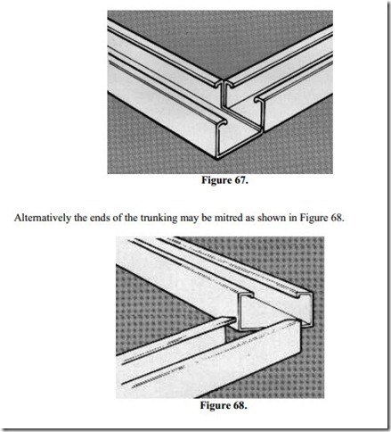
Cut the trunking to length as required. Remove a section of sidewall. Allowing an appropriate gap for expansion, butt the ends together, as shown in Figure 67. This method is only suitable where a moulded fitting is to be used.
Internal Bend
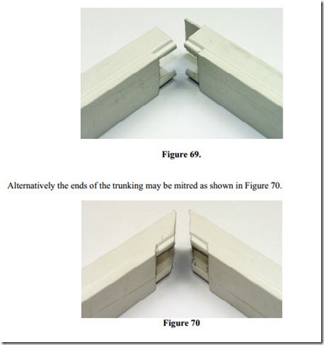
Cut the trunking to length as required. Remove a section of sidewall on one piece. Leave the back of the trunking intact to complete the enclosure. Allowing an appropriate gap for expansion, butt the ends together. See Figure 69.
Ceiling Tee
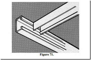
Cut the trunking to length as required. Remove a section of the lip of the through trunking. Allowing an appropriate gap for expansion, butt the tee trunking to the opening, as shown in Figure 71.
Alternatively, an offset tee may be used if the through trunking is run below ceiling height.
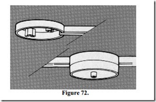
Break out the appropriate knockout(s) in ceiling rose adaptor. Fix ceiling rose adaptor in position. Cut the trunking to length as required and fix to ceiling.
A dummy run of trunking may be fixed to the opposite side of the ceiling rose adaptor in order to achieve a visual balance. Running on through the ceiling rose adaptor will facilitate a second light fitting, see Figure 72.
