Magnetic saturation in induction machines occurs in the main path, at low slip frequencies and moderate currents unless closed rotor slots are used when their iron bridges saturate the leakage path.
In contrast, for high slip frequencies and high currents, the leakage flux paths saturate as the main flux decreases with slip frequency for constant stator voltage and frequency.
The presence of slot openings, slot skewing, and winding distribution in slots, make the problem of accounting for magnetic saturation, in presence of rotor skin effects, when the induction machine is voltage fed, a very difficult task.
Ultimately a 3D finite element approach would solve the problem, but for prohibitive computation time.
Less computation, intensive, analytical solutions have been gradually introduced [9−15]. However, only the starting conditions have been treated (with Is = Ir′ known), with skin effect neglected. Main flux path saturation level, skewing, zig-zag leakage flux have all to be considered for a more precise assessment of induction motor parameters for large currents.
In what follows, an attempt is made to allow for magnetic saturation in the main and leakage path (with skin effect accounted for by appropriate correction coefficients KR, Kx) for given slip, frequency, voltage, motor geometry, no-load curve, by iteratively recalculating the stator magnetization and rotor currents until sufficient convergence is obtained. So, in fact, the saturation and skin effects are explored from no-load to motor stall conditions.
The computation algorithm presupposes that the motor geometry and the no-load curve as Lm(Im), magnetising inductance versus no-load current, is known based on analytical or FEM modeling or from experiments.
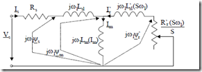
Is Rs j Lω1 sl I’ j L’ω1 rl(S ω1)
Figure 9.23 Equivalent circuit with main flux path saturation and skin effects accounted for
The leakage inductances are initially considered unsaturated (as derived in Chapter 6) with their standard expressions. The influence of skin effect on slot– body specific geometric permeance and on resistances is already accounted for in these parameters.
Consequently, given the slip value, the equivalent circuit with the variable parameter Lm(Im), Figure 9.23, may be solved.
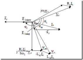
The phasor diagram corresponding to the equivalent circuit in Figure 9.23 is shown in Figure 9.24.
From the equivalent circuit, after a few iterations, based on the Lm(Im) saturation function, we can calculate Is, ϕs, Ir′, ϕr, Im, ϕm.
As expected, at higher slip frequency (Sω1) and high currents, the main flux ψm decreases for constant voltage Vs and stator frequency ω1. At start (S = 1, rated voltage and frequency), due to the large voltage drop over (Rs + j ω1Lsl), the main flux Ψm decreases to 50 to 60% of its value at no-load.
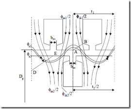
This ψm decreasing with slip and current rise led to the idea of neglecting the main flux saturation level when leakage flux path saturation was approached. However, at a more intrusive view, in the teeth top main flux (Ψm), slot neck leakage flux (Φst1, Φst2), zig-zag leakage flux (Φz1, Φz2), the so-called skewing flux (Φsk1, Φsk2), and the differential leakage flux (Φd1, Φd2) all meet to produce the resultant flux and saturation level (Figure 9.25). It is true that these fluxes have, at a certain point of time, their maxima at different positions along rotor periphery.
In essence, the main flux phase angle is ϕm , while Φst1, Φz1, Φd1, Φst2, Φz2, Φd2, have the phase angles ϕs, ϕr, while Φsk1, Φsk2 are related to rotor current uncompensated mmf and thus is linked to ϕr again. As slip varies, not only Is, Ir′, Im vary but also their phase angles: especially ϕs and ϕr′ with ϕm about the same. The differential leakage fluxes (Φd1, Φd2) are not shown in Figure 9.25 though they also act within airgap and teeth top zones, AB and DE.
To make the problem easy and amenable to computation, it is assumed that when saturation occurs in some part of the machine, the ratios between various flux contributions to total flux remain as they were before saturation.
The case of closed rotor slots is to be treated separately. Let us now define the initial expressions of various fluxes per tooth and their geometrical specific leakage permeances.
In a similar manner, the zig-zag fluxes Φz1 and Φz2 are
Φz1 = AT1µ0lstackλz1
Φz2 = AT2µ0lstackλz2 (9.59)
![]()
![]() AT1 = n Is s 2; AT2 = n I’r r 2; From (9.56) and (9.59) nr is
AT1 = n Is s 2; AT2 = n I’r r 2; From (9.56) and (9.59) nr is
nr = I’I= n Ks w1 NNsr (9.60)
|
The unsaturated zig-zag specific permeances λz1 and λz2 are [5] |
|
|
(9.61) |
|
|
(9.62) |
|
|
a1 = t 5g1( (+ b+os )− b) or2 |
(9.63) |
t 5g1 bos
|
a 2 = t2 5tg2 (5gbor+ borb)os The slot neck fluxes Φst1 and Φst2 are straightforward. |
(9.64) |
The differential leakage, specific permeance λd1,2 may be derived from a comparison between magnetization harmonic inductances Lmν and the leakage inductance expressions Lsl and Lrl′ (Chapter 7).
|
Lmν = 6π20 (p1/ν)gK 1lstackc ( W K+1Ksteethwν ) |
(9.67) |
|
Lsl = 2µ0 Wp q112 (λss + λz1 + λendcon1 + λst1 + λd1) |
(9.68) |
|
Lsr = 2µ0 Wp q112 (λsr + λz2 + λendcon2 + λd2 + λst2 + λsk2 ) |
(9.69) |
µ (τ ν) ( )2
|
1 1 λd2 = λm1 Ns (τd2 − ∆τd2 ); ∆τd2 = Kz2 2p1 2 |
(9.70) |
τd1 = π2  27 q −1; ∆τd1 = Kz1 91q2
Nr Nr
πp1 2
![]() τd2 = Nrπp1 sin π2p1πN⋅pskew1rN⋅skewr 2 −1
τd2 = Nrπp1 sin π2p1πN⋅pskew1rN⋅skewr 2 −1
sin2 Nr
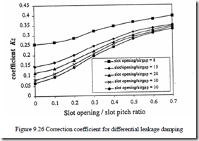
The coefficient Kz1 and Kz2 are found from Figure 9.26.
The slot-specific geometric permeances λss and λsr, for rectangular slots, with rotor skin effect, are
λss = 3hbss + λst1 (9.71)
λsr = 3hbrr ⋅KX + λst2; Kx −skin effect correction (9.72)
The most important “ingredient” in leakage inductance saturation is, for large values of stator and rotor currents, the skewing (uncompensated) mmf.
9.7.1. The skewing mmf
The rotor (stator) slot skewing, performed to reduce the first slot harmonic torque (in general) has also some side effects such as: a slight reduction in the magnetization inductance Lm accompanied by an additional leakage inductance component, L′rskew. We decide to “attach” this new leakage inductance to the rotor as it “disappears” at zero rotor current
To account for Lm alteration due to skewing, we use the standard skewing factor Kskewconv .
![]() sin π2 skew / m q1 1 ; Kskewconv ≈ 0.98−1.0 (9.73)
sin π2 skew / m q1 1 ; Kskewconv ≈ 0.98−1.0 (9.73)
and include a rotor current linear dependence to make sure that the influence disappears at zero rotor current,
Kskew =1− (1− Kskewconv )I ‘Irs (9.74)
skew–is the skewing in stator slot pitch counts.
To account for the skewing effect, we first consider the stator and rotor mmf fundamentals for a skewed rotor.
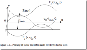
As the current in the bar is the same all along the stack length (with interbar currents neglected), the rotor mmf phasing varies along OY, beside OX and time (Figure 9.27) so the resulting mmf fundamental is
+ F2m sin πτ x − π2 f t1 − ϕ − ϕ( s r )− m qπ1 1 skew lstacky (9.75)
− lstack ≤ y ≤ lstack
2 2
We may consider this as made of two terms, the magnetization mmf F1mag and the skewing mmf F2skew.
F x,y,t( )= F1mag + F2skew (9.76)
F1mag = F1m sin πτ x − π2 f t1 +
+ F2 π skew y ⋅sin πτ x − π2 f t1 − ϕ − ϕ( s r ) (9.77) m cos m q1 1 lstack
π y ⋅cos πτ x − π2 f t1 − ϕ − ϕ( s r ) (9.78) F2skew = −F2m sin m q1 1 skew lstack
F1mag is only slightly influenced by skewing (9.77) as also reflected in (9.73).
On the other hand, the skewing (uncompensated) mmf varies with rotor current (F2m) and with the axial position y. It tends to be small even at rated current in amplitude (9.78) but it gets rather high at large rotor currents. Notice also that the phase angle of F1mag (ϕm) and F2skew (ϕr) are different by slightly more than 900 (Figure 9.24), above rated current,
ϕskew = ϕ − ϕr m (9.79)
We may now define a skewing magnetization current Imskew:
Imskew = ±Im ATAT12m sin(π2p SKW / N1 1 s ) (9.80)
Example 9.6. The skewing mmf
Let us consider an induction motor with the following data: no-load rated current: Im = 30% of rated current; starting current. 600% of rated current; the number of poles: 2p1 = 4, skew = 1 stator slot pitch; number of stator slots Ns =
36. Assessment of the maximum skewing magnetization current Imskew/Im for starting conditions is required.
Solution
Making use of (9.80), the skewing magnetization current for SKW1 = ±skew.
ImskewIm = ± ATAT12m sin π2p skew /1(Ns 2) = ± II ‘mr sin π⋅4 136⋅ / 2 ≈
≈ ± IIstartm ⋅0.15643 = ± 60030%% ⋅0.15643 = ±3.1286!
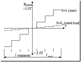
This shows that, at start, the maximum flux density in the airgap produced by the skewing magnetization current in the extreme axial segments will be maximum and much higher than the main flux density in the airgap, which is dominant below rated current when Imskew becomes negligible (Figure 9.28).
Figure 9.28 Skewing magnetization current produced airgap flux density
Airgap flux densities in excess of 1.0 T are to be expected at start and thus heavy saturation all over magnetic circuit should occur.
Let us remember that in these conditions the magnetization current is reduced such that the airgap flux density of main flux is (0.6 – 0.65) of its rated value, and its maximum is phase shifted with respect to the skewing flux by more than 900 (Figure 9.24). Consequently at start (high currents), the total airgap flux density is dominated by the skewing mmf contribution! This phenomenon has been documented recently through FEM [16]. Dividing the stator stack in (Nseg + 1) axial segments, we have:
SKW1 = 0.0, skewNseg , skew2 (9.81)
Now, based on Imskew, from the magnetization curve (Lm(Im)), we may calculate the magnetization inductance for skewing magnetization current Lm(Imskew). Finally we may define a specific geometric permeance for skewing λsk1.
![]() λsk1 = N Ks Lw1mW n(I1mskewsµ0)lstack (9.82)
λsk1 = N Ks Lw1mW n(I1mskewsµ0)lstack (9.82)
W1–turns/phase. λsk1 depends on the segment considered (6 to 10 segments are enough) and on the level of rotor current.
Now the skewing flux/tooth in the stator and rotor is
|
Φsk1 = AT sin2 2p SKW1Ns 1µ0lstackλsk1 |
(9.83) |
|
Φsk2 = Φsk1 Ns |
(9.84) |
π
Nr
In (9.83), the value of Φsk1 is calculated as if the value of segmented skewing is valid all along the stack length. This means that all calculations will be made nseg times and then average values will be used to calculate the final values of leakage inductances.
Now if the skewing flux occurs both in the stator and in the rotor, when the leakage inductance is calculated, the rotor one will include the skewing permeance λsk2.
λsk2 = λsk1 NNsr (9.85)
9.7.2. Flux in the cross section marked by AB (Figure 9.25)
The total flux through AB, ΦAB is
ΦAB = Φ2m1 + Φ2sk1 + Φz1 + Φz2 + Φst1 (9.86)
Let us denote
Cm1 = 2ΦΦm1AB Csk1 = 2ΦΦsk1AB Cz1 = ΦΦABz1 (9.87)
Φst1 Cz2 = ΦΦABz2 (9.88)
Cst1 = ΦAB
These ratios, calculated before slot neck saturation is considered, are also taken as valid for a total leakage saturation condition.
There are two different situations: one with the stator tooth saturating first and the second with the saturated rotor teeth.
9.7.3. The stator tooth top saturates first
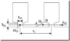
Making use of Ampere’s and flux laws, the slot neck zone is considered (Figure 9.29).
|
(t1 − bos )H1 + b Hos 10 = AT1 The total flux through AB is |
(9.89) |
|
ΦABsat = AB l⋅ stack ⋅B1 |
(9.90) |
On the other end, with Cst1 known from unsaturated conditions, the slot neck flux Φst1 is
|
Φst1 = Cst1ΦABsat = µ0H h l10 os stack From (9.89) – (9.91), we finally obtain |
(9.91) |
|||
|
AT1 − t ‘H1 1 |
||||
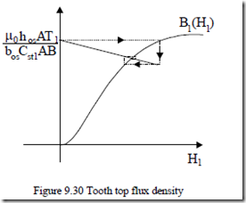
B1 = µ0hos b Cos st1AB ; t ‘1 = t1 − bos (9.92) Equation (9.92) corroborated with the lamination B1(H1) magnetization curve leads to B1 and H1 (Figure 9.30).
An iterative procedure as in Figure 9.30 may be used to solve (9.92) for B1 and H1. Finally, from (9.90), the saturated value of (ΦAB)sat is obtained.
Further on, new values of various teeth flux components are obtained.
Φ2m1 sat = Cm1(ΦAB )sat
(Φsk1)sat = Csk1(ΦAB )sat (9.93)
(Φz1)sat = Cz1(ΦAB )sat
(Φst1)sat = Cst1(ΦAB )sat
The new (saturated) values of stator leakage permeance components are
|
(9.94) |
(λst1)sat = AT(Φµst1l)sat
The end connection and differential geometrical permeances λendcon and λd1 maintain, in (9.68), their unsaturated values, while (λst1)sat and (λz1)sat (via (9.94)) enter (9.68) and thus the saturated value of stator leakage inductance Lsl for given stator and rotor currents and slip is obtained.
We have to continue with the rotor. There may be two different situations.
9.7.4. Unsaturated rotor tooth top
In this case the saturation flux from the stator tooth is “translated” into the rotor by the ratio of slot numbers Ns/Nr.
![]() (λst2 )sat = (ATΦst11µ)sat0lstackNNsr
(λst2 )sat = (ATΦst11µ)sat0lstackNNsr
![]() (λz2 )sat = (ATΦz11µ)sat0lstackNNsr (9.95)
(λz2 )sat = (ATΦz11µ)sat0lstackNNsr (9.95)
(λsk2 )sat = λsk1 NNsr
In Equation (9.95) it is recognised that the skewing flux “saturation” is not much influenced by the tooth top flux zone saturation as it represents a small length flux path in comparison with the main flux path available for skewing flux.
By now, with (9.69), the saturated rotor leakage inductance Lrl′ may be calculated. With these new, saturated, leakage inductances, new stator, magnetization, and rotor currents are calculated.
The process is repeated until sufficient convergence is obtained with respect to the two leakage inductances. A new slip is then chosen and the computation cycle is repeated.
9.7.5. Saturated rotor tooth tip
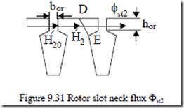
In this case, after the AB zone was explored as above the DE cross section is investigated (Figure 9.31). Again the Ampere’s law across tooth tip and slot neck yields
|
(t2 − bor )H2 + b Hor 20 = AT2 |
(9.96) |
|
Figure 9.31 Rotor slot neck flux Φst2 The flux law results in |
|
|
ΦDE = Φ + Φ1 ( st2 )sat ; B2 = µ0H20 |
(9.97) |
where Φ = Φ1 ABsat NNsr (9.98)
Also (Φst2 )sat = DE l⋅ stack ⋅B2 (H2 ); t ‘2 = t2 − bor (9.99)
(Φst2 )sat = µ0H20hos stackl = µ0hor (AT2 b−ort ‘H2 2 )lstack (9.100)
![]() Finally, B2 (H2 )= lstack1DE ΦABsat NNsr + µ0hor (AT2 b−ort ‘H2 2 )lstack (9.101)
Finally, B2 (H2 )= lstack1DE ΦABsat NNsr + µ0hor (AT2 b−ort ‘H2 2 )lstack (9.101)
Equation (9.101), together with the rotor lamination magnetization curve, B2(H2), is solved iteratively (as illustrated in Figure 9.30 for the stator).
Then,
(λst2 )sat = (Φst2Φ)st2sat λst2 ; λst2 = hboror (9.102)
Φst2 = µ0AT l2 stackλst2 (9.103)
The other specific geometrical permeances in the rotor leakage inductance (λz2)sat and (λsk2)sat are calculated as in (9.95). Now we calculate the saturated value of Lrl′ in (9.69). Then, from the equivalent circuit, new values of currents are calculated and a new iteration is initiated until sufficient convergence is reached.
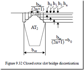
9.7.6. The case of closed rotor slots
Closed rotor slots (Figure 9.32) are used to reduce starting current, noise, vibration, and windage friction losses though the breakdown and starting torque are smaller and so is the rated power factor.
The slot iron bridge region is discretized in 2n + 1 zones of constant (but distinct) permeability µj. A value of n = (4 – 6) suffices. The Ampere’s and flux laws for this region provide the following equations:
n b0H0 + 2∑H j = AT2 (9.104)
1
B h0 0 = B h1 1 = B h2 2 =K= B hn n (9.105)
Given an initial value for B0, for given AT2, B1, …, Bn are determined from (9.105). From the lamination magnetization curve, H0, H1, …, Hn are found. A new value of AT2 is calculated, then compared with the given one and a new B0 is chosen. The iteration cycle is revisited until sufficient convergence is obtained.
Finally, the slot bridge geometrical specific permeance (λst2)sat is
![]() (λst2 )sat = hb00 B0 + 2b0 B11 +K+ 2hbn0 µB0Hn n (9.106) µ0H0 h1 µ0H1
(λst2 )sat = hb00 B0 + 2b0 B11 +K+ 2hbn0 µB0Hn n (9.106) µ0H0 h1 µ0H1
All the other permeances are calculated as in previous paragraphs.
9.7.7. The algorithm
The algorithm for the computation of permeance in the presence of magnetic saturation and skin effects, as unfolded gradually so far, can be synthesized as following:
• Load initial data (geometry, winding data, name-plate data etc.)
• Load magnetization file: B(H)
• Load magnetization inductance function Lm(Im) – from FEM, design or tests
• Compute differential leakage specific permeances
• for S = Smin, Sstep, Smax for SKW1 = 0:skew/nseg:skew compute unsaturated specific permeances while magnetization current error < 2%
compute induction motor model using nonlinear Lm(Im) function end;
Save unsaturated parameters 1. if case = closed rotor slots;
compute closed rotor case; else
while H1 error < 2%; compute stator saturation case; end;
compute unsaturated rotor case;
if case = saturated rotor; while H2 error < 2%; compute saturated rotor case
end; end.
Compute saturated parameters; compare them with those of previous cycle and go to 1. Return to 1 until sufficient convergence in Lsl and Lrl′ is reached. end.
end (axial segments cycle)
end (slip cycle)
Save saturated parameters for SKW1 = 0:skew/nseg:skew;
Compute saturated parameters average values; plot the IM parameters (segment number, slip);
Compute IM equivalent circuit using an average value for each parameter (for the nseg, axial segments);
Compute stator, rotor, magnetization current, torque, power factor versus slip;
Plot the results end.
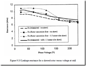
Applying this algorithm for S = 1 an 1.1 kW, 2 pole, three-phase IM with skewed rotor, the results shown on Figure 9.33 have been obtained [18]. Heavy saturation occurs at high voltage level. The model seems to produce satisfactory results.
![clip_image005[4] clip_image005[4]](http://machineryequipmentonline.com/electric-equipment/wp-content/uploads/2017/03/clip_image0054_thumb2.gif)
