Fluorescent Lighting
These are the most common of the discharge lamps because they are very efficient and are suitable for internal applications. The lamps are made in a variety of lengths from 150 mm up to 2400 mm ( 8 Watt to 125 Watt.) and are filled with mercury vapour at low pressure. Cap type is G5 or G13.
The radiated light is almost invisible but it is converted to visible light by a coating of fluorescent powder on the inner tube surface. By using different combinations of fluorescent powders, it is possible to control the colour of the light produced. White lamps are most efficient, but the appearance of coloured surfaces illuminated by them may be altered ( poor colour rendering ).
A high voltage is needed to cause the tube to strike ( discharge ) and there are several methods of providing this voltage. Oxide coated filaments are situated at each end of the fluorescent tube. The resistance of these two filaments should be approximately the same. Discharge takes place when a high voltage is applied between the two filaments located at each end of the tube.
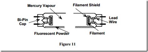
Figure 11 illustrates the component parts the fluorescent lamp.
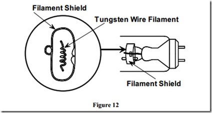
Figure 12 illustrates one end of a fluorescent lamp and includes an exploded view of the tungsten wire filament and the filament shield.
Operation of a Fluorescent Fitting
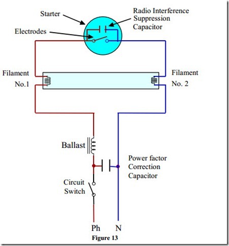
Refer to Figure 13, when the supply is switched on, the circuit is completed via the phase, circuit switch, ballast ( choke ), lamp filament No.1, starter neon gas ( contact open ), lamp filament No.2, and the neutral.
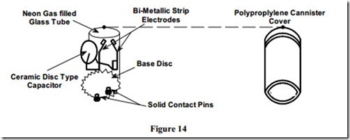
The filaments, which are coated in oxide, become heated and emit an electron cloud. The tube will be seen to glow at each end. The current which is flowing through the filaments and through the starter causes the neon gas in the starter to glow. The construction of the starter is such that it contains a fixed electrode and a bi-metallic electrode. The heat produced by the neon gas causes the bi-metallic electrode to bend and touch the fixed electrode. See Figure 14.
Immediately, the glow ceases and cooling takes place, which in turn causes the electrodes to part. This means that the ballast is now open circuited, and it produces a high voltage. This high voltage is applied across the lamp from Filament No.1 to Filament No. 2 and causes it to strike.
The starter now has a very low voltage across its electrodes and as a result the neon gas does not glow. The contact remains open. The ballast limits the operating current to a pre-determined value. The ballast is an inductive load and it causes power factor problems. To overcome this, a capacitor is connected as shown in Figure 13. This capacitor has no other function in the circuit. The ceramic disc type capacitor across the contact in the starter is for radio interference supression only. The circuit will continue to function if either one, or both capacitors are removed.


