Two electric motors can be interlocked so that the second one cannot run unless the first one is running. This may be necessary to prevent plugging of a materials handling system. For example, if a conveyer stops, it may be desirable to shut down the silo unloader feeding the conveyer. Another common interlock t~chnique is used to prevent two large motors from operating at the same time. This may be desirable to keep the electrical demand as low as possible in order to reduce the monthly electric bill. Extra interlock contacts can be added to a magnetic motor starter, Figure 17 31. Normally open and normally closed interlocking contacts are available. In Figure 17 32, motor B will operate only if motor A is operating. In Figure 17 33, motor D cannot operate if motor C is operating. In ladder diagrams, only the control circuits are shown. All parts labeled A are inside motor starter A, and similarly with parts B, C, and D. A confusing aspect of a ladder control diagram is that parts normally located physically together in the actual wiring may be located at any appropriate location on the ladder diagram
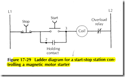
ladder diagram for a start stop station controlling a magnetic motor starter


