What Are Process Functions?
When in use, an audio power amplifier is always but part of some greater system. In domestic audiophile and even recording studio systems, it is commonplace for power amplifiers to have no gain controls and to be devoid of any processing functions.
However, in professional music PA applications, by contrast, it is the exception to find power amplifiers without panel gain controls (really attenuators). This facility turns into a system processing function when the gain control element becomes remote controllable, most particularly when all the amplifiers in a system or grouping are so equipped and also when the rate of gain control change is fast enough for it to be used dynamically.
Common Gain Control (Panel Attenuator)
The most common, almost universal form of “gain control” is passive attenuation, set usually via a panel knob, with a rotary pot or potentiometer.
Characteristics
As “voltage matching” is the norm for modern audio, pots are nearly always wired in the voltage divider mode, where the wiper is the output. At this point, the source impedance seen varies, up to a maximum of a quarter (25%) of the pot’s rated value (i.e., the end-to- end resistance) at half setting. At the pot’s maximum and minimum settings, the source impedance reaches a few ohms above zero, which is usually much less than the preceding signal source’s impedance.
Common Values
In audio power amplifiers, the pot’s value is commonly 5 or 10 kΩ in professional and audiophile grade equipment and 20, 50, or 100 kΩ or even higher in “consumer” grade
equipment. The lower pot values offer lower maximum impedances at half-setting, for example, just 2500 Ω (2.5 kΩ) for a (10 kf) pot. This lessens the scope for noise pickup in the inevitably unbalanced and relatively sensitive part of the amplifier circuitry where the pot is placed.
Audio Taper
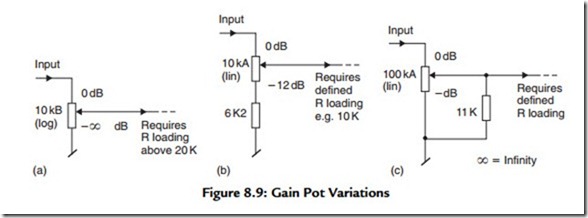
These considerations are true for ordinary pots with an audio taper, that is, those marked ‘log’ or ‘B’. As shown wired in Figure 8.9(a), these normally sweep over the maximum possible range of level setting, from a purely nominal ∞ (hard CCW or “shut off,”
really more like –60 to –70 dB) up to 0 dB (maximum level). The “audio taper” alias logarithmic resistance change per ° rotation makes the change in sound level reasonably constant with rotation. The full span and audio taper are relevant when a pot is needed to act sometimes as volume control, where output levels very much lower than the power
x = Infinity
amplifier’s capability are useful. It’s also relevant where a quick sweep to ∞ (infinite
attenuation) may be needed as a mute—to turn off the signal in one speaker, say—
without switching off or unplugging anything.
The Right Range
In many applications, the range offered by a raw pot is far too wide. In other industries employing pots, a vernier or a multiturn mechanism is added between the knob and shaft to aid fine settings. However, these are eschewed by modem professional audio operators, partly because of an ingrained fear of the loss of instant sweep control and because of relatively high cost versus relative fragility. There is also the false sense of alignment suggested by the verniers’ 3 or 4 figure scale; scales on different amplifiers would be strictly incomparable, owing to most pots’ poor tolerances, particularly good-sounding log pots. In the past 20 years, variations of 5 to 25% (or 0.5 dB to 3 dB) have remained the norm for the resistance mismatch between different pots at the same mechanical setting.
Linear Variants
Using a linear (A) pot and a fixed resistor, Figure 8.9(b) shows how adjustment range is restricted to the “top” 12 dB, that is, 0 dB to –12 dB. For system adjustment, this may be more usefully expressed as +/–6 dB. This range of adjustment is preferable for active crossover-based and arrayed systems, where the gain of individual amplifiers benefits from close adjustments and only needs this limited range. In practice, switched (say) –20 dB and ∞ settings are then required. Note that the impedance vs. rotation relation is naturally slightly changed—the highest source impedance is here less at about 20% (rather than 25%) of the pot.
Returning to the full-scale mode, a linear pot may alternatively be used [Figure 8.9(c)], with a fixed resistor used for “law faking.” This converts the linear law to a log-like curve, if the pot and resistor values are kept within tight limits; this approach can give approximations of an audio taper that are at least more consistent than most log pots, which are made by butting n different-valued linear track segments together. Note that the pot’s effective value is here a tenth of its rated value after the law faking resistor
is included. As a result, the pot shown in Figure 8.9(c) looks like a 10 kf2 pot to the load. However, the maximum source resistance is, as with the audio taper, at the 50% attenuation point and is just about 10% from maximum.
As in other analogue audio circuits, the placement of any gain control device requires careful considerations in regard to considering trade-offs in headroom and SNR. But in power amplifiers having a minimum path, there is not much choice for location. They all end up after the input is unbalanced but before it is raised far.
Placement couldn’t be contemplated after the point of signal passing to the input of the power stage, for example, as pots having film tracks (cf. wire wound) that are suitable for audio by virtue of low rotation noise are unsuited to high dissipation. In any event, most power stage topologies don’t have a place for inserting a single-ended, passive voltage divider, don’t like having their gain widely changed, and are moreover wrapped around by NFB.
Adequate CMR (at the amplifier’s input) demands good balancing, which in turn relies on resistance matching to better than at least 0.5%, and since even makers of very expensive, high specification pots have problems maintaining matching between two or more sections to even 2%, over the entire travel, pots passing audio have to be placed after the input signal has been converted to single ended, that is, after the debalancer (DTSEC). Virtually all power amplifier gain pots (or whatever other gain control devices) end up thusly sandwiched. A few are used in active mode, where the pot is used in the NFB loop, of either an added line-level stage or even a gain-change tolerant power stage. This seems smart but it has its own problems.
Fixed Install
In amps principally intended for fixed installation, whether for a home cinema or public venues, and where power amplifier gain trims are needed or helpful for setting up, “knobless” gain controls are welcomed. Here, shafts are normally recessed and can only be turned with a screwdriver. This avoids not just casual tampering, but knobs being moved (and settings lost) by accidental brushing, sweeping, or knocking. A collet nut may be included. When tightened, the setting will then be immune to attack by a screwdriver, as well as vibration creep. As a further discouragement to “let’s turn this up,” such controls may be placed on the rear panel of the amp or hidden behind cover plates.
8.6.2 Remotable Gain Controls (Machine Control)
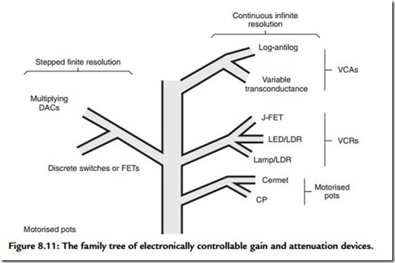
Pots are mostly made to interface with human fingers via knobs. When a sound system moves past the point where a single driver in each band can handle the power required or where Ambisonic or other multichannel sound is contemplated, remote control opens the door to “intelligent” control of loudspeaker systems and clusters, including balancing and tweaking directivity, imaging, and focusing, by machines and via wires and radio links. The gain of an amp can be controlled by a variety of electronic means (Figure 8.11). The purely electronic means are fast enough to perform additional, true processing functions, for example, limiting.
Usually a motor connects to the same shaft as a knob, but the latter via a slipping clutch. Either may override. This keeps the simplicity but shares the wide setting tolerance, sonic, and some of the mechanical limitations, of ordinary pots, for example, fragile shaft, relatively low setting speed. Which overrides the other depends on which way confidence most leans—toward human fingers or computers! Control circuitry is needed to decode remote command signals, which may be a variety of formats. Special driver ICs (e.g., BA series made by Rohm in Japan) make design and manufacture easy but might pose major replacement headaches to some owners in the future.
Voltage-Controlled Amplifiers
Commonly called a voltage-controlled amplifier, most are used as VC attenuators, usually as a solid state and always an analogue circuit. Most are ICs based around one of a limited number of proprietary schemes, which are made (or licensed, e.g., That Corp. in U.S. licenses, National in Japan) by one of three main patent holders, all in the United States.14 Otherwise they are based on a discrete circuit or on a consumer grade ‘OTA’ IC. Gain is accurately settable to within a fraction a dB, down to at least –70 dB and even into positive gain with some parts. Gain is always defined by an analogue control voltage (or current) that may be derived locally after decoding from a digital line
or buss. Refined VCAs introduce considerable added circuitry into the signal path, which may defeat its own purpose. The simplest parts add two stages. They may boast low noise but it is at the expense of exposing the unnatural distortion patterns they create. The best performers add as many as five sequential stages and more than 5 op-amps may be required. If part quality is not to be compromised, the added cost seems high. Operating speed with most types can be very high, under 1 ItS. In this way, VCAs and all the following contrivances are applicable to dynamic functions, up to the fastest meaningful audio peak limiting.


