Automatic Float Switch
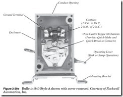
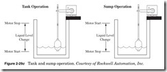
Float switches provide automatic control for motors that pump liquids from a sump or into a tank (Fig. 2-29a, b, and c). The switch must be
• Liquid Level Sensitivity From 2 to 5 Inches
• 0.6 to 3.8 Ibs Switch Operating Force
• 2 or 3 Pole Contact Configurations
• Tank to Sump Convertibility
• NEMA A600 and NEMA N300 Contact Ratings
• Type 1, Type 4, and Type 7 & 9 Enclosures
installed above the tank or sump, and the float must be in the liquid for the float switch to operate. For detailed specifications, see Allen Bradley at www.ab.com.
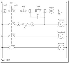
Line 1 Terminal 1, contact of Hand/Off/Auto Selector switch closed in the Hand position as indicated by the XOO, Normally Closed Stop button, terminal 2. Down one line, Normally Open contact of M1 starter. Normally Open Start push button, terminal 3, motor starter with Normally Closed overload contact.
Line 2 Contact of Hand/Off/Auto Selector switch closed in the Auto position as indicated by the OOX, terminal 4, Normally Open contact of the float switch, connection to starter circuit, green pilot light.
Line 3 Contact of Hand/Off/Auto Selector switch closed in the Hand position as indicated by the XOO, amber pilot light.
Line 4 Contact of Hand/Off/Auto Selector switch closed in the Off position as indicated by the OXO.
Figure 2-29d is an example of a sump operation:
Hand In the Hand position the Stop and Start buttons can be used to operate the pump, and the amber pilot light will be on.
Off In the Off position the circuit is inactive and the red pilot light will be on.
Auto A float operator assembly is attached to the float switch by a rod, chain, or cable. The float switch is actuated based on the location of the float in the liquid. The float switch contacts are closed when the float forces the operating lever to the up position. As the liquid level rises, the float and operating lever move upward. When the float reaches a preset high level, the float switch contacts close when the select switch is in the Auto position, activating the circuit and start- ing the motor and turning on the green pilot light. As the liquid level falls, the float and operating lever move downward. When the float reaches a preset low level, the float switch contacts open, deactivating the circuit and stopping the motor.
Tank operation is the opposite of sump operation.
Pressure Switch
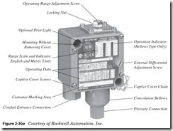
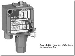
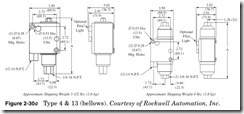
Pressure switches provide automatic control for motors that pump pres- sure into a line (Fig. 2-30a, b, and c). The switch must be installed in the line to be monitored. There are two circuits, with one Normally Open and one Normally Closed contact per circuit.
For detailed specifications, see Allen Bradley at www.ab.com.
Bulletin 836T Pressure Controls
• Operating ranges from 30 in. Hg vacuum…5000 psi
• Independently adjustable range and differential
• Copper alloy and stainless steel bellows
• 2- and 4-Circuit contact block
• Pressure difference controls available
• 1/4 in. and 3/8 in. N.P.T. and O-ring straight thread connections
• Type 4 & 13 and Type 7 & 9 and 4 & 13 combination enclosures
Dimensions in inches (millimeters). Dimensions are not intended to be used for manufacturing purposes.
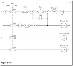
Shown in Fig. 2-30d:
Line 1 Terminal 1, contact of Hand/Off/Auto Selector switch closed in the Hand position as indicated by the XOO, Normally Closed Stop button, terminal 2. Down one line, Normally Open contact of M1
starter. Normally Open Start push button, terminal 3, motor starter with Normally Closed overload contact.
Line 2 Contact of Hand/Off/Auto Selector switch closed in the Auto position as indicated by the OOX, terminal 4, Normally Closed con- tact of the pressure switch, connection to starter circuit, green pilot light.
Line 3 Contact of Hand/Off/Auto Selector switch closed in the Hand position as indicated by the XOO, amber pilot light.
Line 4 Contact of Hand/Off/Auto Selector switch closed in the Off position as indicated by the OXO.
Figure 2-30d is an air compressor:
Hand In the Hand position, the Stop and Start buttons can be used to operate the compressor, and the amber pilot light will be on.
Off In the Off position the circuit is inactive and the red pilot light will be on.
Auto The pressure switch is actuated based on the air pressure in the line being monitored. The pressure switch contacts are closed; when the air pressure level decreases, the pressure in bellows decreases. When the pressure reaches a preset low level, the pres- sure switch contacts close with the select switch in the Auto position activating the circuit and starting the motor and turning on the green pilot light. As the pressure level increases, the pressure in the bellows increases. When the air pressure reaches a preset high level, the pressure switch contacts open, deactivating the circuit and stopping the motor.
Temperature Switch
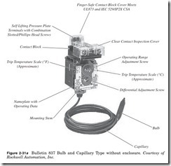
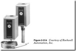
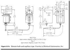
Bulletin 837 temperature controls are heavy-duty control circuit devices used in industrial applications where the temperature must be main- tained within preset limits (Fig. 2-31a, b, and c). These devices use a vapor pressure technology to sense changes in temperature. The pres- sure change is transmitted to the bellows through a bulb and capillary tube. Pressure in the system changes in proportion to the temperature of the bulb. Most styles make use of bulbs and capillaries filled with a temperature-responsive liquid for detecting temperature changes.
For detailed specifications, see Allen Bradley at www.ab.com.
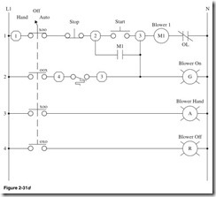
Shown in Fig. 2-31d:
Line 1 Terminal 1, contact of Hand/Off/Auto Selector switch closed in the Hand position as indicated by the XOO, Normally Closed Stop button, terminal 2. Down one line, Normally Open contact of M1 starter. Normally Open Start push button, terminal 3, motor starter with Normally Closed overload contact.
Line 2 Contact of Hand/Off/Auto Selector switch closed in the Auto position as indicated by the OOX, terminal 4, Normally Closed contact of the temperature switch, connection to starter circuit, green pilot light.
Line 3 Contact of Hand/Off/Auto Selector switch closed in the Hand position as indicated by the XOO, amber pilot light.
Line 4 Contact of Hand/Off/Auto Selector switch closed in the Off position as indicated by the OXO.
Figure 2-31d is a blower circuit:
Hand In the Hand position the Stop and Start buttons can be used to operate the blower, and the amber pilot light will be on.
Off In the Off position the circuit is inactive and the red pilot light will be on.
Auto The temperature switch is actuated based on the temperature in the duct being monitored. The temperature switch contacts are closed; when the temperature level raises, the pressure in bellows increases. When the temperature reaches a preset level, the tempera- ture switch contacts close with the select switch in the Auto position, activating the circuit, starting the motor, and turning on the green pilot light. As the temperature level decreases, the pressure in the bellows decreases. When the temperature reaches a preset low level, the pressure switch contacts open, deactivating the circuit and stop- ping the motor.
