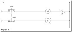
In Fig. 2-21, the push buttons are maintained; one contact is open and one contact is closed. This operator can have a maximum of two Normally Open and two Normally Closed. Typical use is Start-Stop sta- tion. For detailed specifications, see Allen Bradley at www.ab.com.
Shown in Fig. 2-21a:
Line 1 Normally Open Start button motor start M1 with Normally Closed overload relay. When the Start button is pressed, the motor will run and the red pilot light will be off.
Line 2 Normally Closed Stop button. When it is pressed, the motor will stop and the red pilot light will be on.
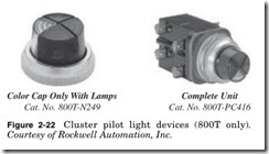
The cluster pilot lights in Fig. 2-22 can have 2, 3, or 4 lights with different-color lenses. For detailed specifications, see Allen Bradley at www.ab.com.
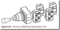
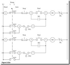
In Fig. 2-23 there is a 4-position toggle switch. This operator can have 1, 2, 3, or 4 positions. The operator can be momentary or maintained- position; in Fig. 2-23 it is a maintained operator. This operator can have multiple contacts. It is recommended that it have a maximum of four 2 × 2 blocks. This can give it a total of 8 contacts, which can be Normally Open or Normally Closed. If more than this is needed, then consider using a relay. Typical use is for Hand operation 1 operation 2 Auto opera- tor. These operators can use the contacts in Fig. 2-3. For detailed specifica- tions, see Allen Bradley at www.ab.com.
Line 1 4-position toggle Selector is in the Hand position as indicated by the XOOO, and the Stop button is closed. When the Start button is pressed, the motor starter will be energized and the M1 contact will close. Pump 1 will run until the Stop button is depressed or the select switch position is changed.
Line 2 4-position toggle selector is in the pump 1 or Auto position as indicated by the OXOO and the OOOX, and the float switch is closed. Pump 1 will run until the liquid level drops and opens the float switch.
Line 3 4-position toggle selector is in the Hand position as indicated by the XOOO, and the Stop button is closed. When the Start button is pressed, the motor starter will be energized and the M2 contact will close. Pump 2 will run until the Stop button is depressed or the select switch position is changed.
Line 4 4-position toggle selector is in the pump 2 or Auto position as indicated by the OOXO and the OOOX, and the float switch is closed. Pump 2 will run until the liquid level drops and opens the float switch.
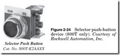
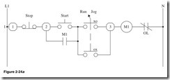
The 2-position Selector switch with push-button operator in Fig. 2-24 can have multiple contacts. It is recommended that it have a maximum of two 1 × 1 blocks. This can give it a total of 4 contacts, which can be two Normally Open and two Normally Closed. The sleeve is the Selector switch; it can be moved left and right. Typical use is for the run jog operator. These operators can use the contacts in Fig. 2-3. For detailed specifications, see Allen Bradley at www.ab.com.
Shown in Fig. 2-24a:
Line 1 Terminal 1, Normally Closed push button, terminal 2. Down one line, Normally Open M1 contact. Down one line, contact of the 2-position Selector switch closed in the jog position indicated by the OX. Next on line 1, contact of the 2-position Selector switch closed in the run position indicated by the XO. Terminal 3, M1 motor starter with Normally Closed overload contact. With the run jog in the run position, pressing the Start button will energize the M1 motor starter and close the M1 contact. The Motor will run until the Stop button is pressed or the Selector switch is changed. With the run jog Selector switch in the jog position, pressing the Start button will energize motor starter M1 as long as the button is pressed.
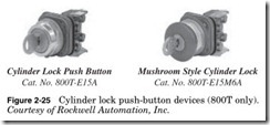
The operators in Fig. 2-25 can be locked in the depressed position. The button is available in three modes:
Spring bolt Lock can be set with a key when button is in the Out position. Button will lock when depressed. Key is removable in any position. One Normally Open and one Normally Closed lock position in.
Dead bolt A Button can only be operated with the key in the lock. Key is removable in locked position only. One Normally Open and one Normally Closed lock position in or out.
Dead bolt B Button can be operated with or without the key inserted in the lock. Key is removable in any position. One Normally Open and one Normally Closed lock position in or out.
Typical use is for emergency stop on motor circuit or on an EPO circuit.
For detailed specifications, see Allen Bradley at www.ab.com.
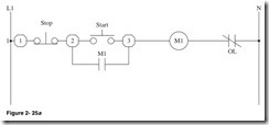
Shown in Fig. 2-25a:
Line 1 Terminal 1, then Normally Closed Stop button, terminal 2 Normally Open Start button. Down one line, Normally Open M1 con- tact. Motor starter M1 with Normally Closed overload contact. When the Start button is pressed, then the M1 motor will be energized and the motor will run until the Stop button is pressed.
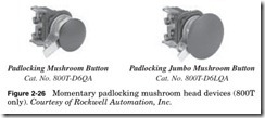
The mushroom push buttons in Fig. 2-26 can have one Normally Open or one Normally Closed or one Normally Open and one Normally Closed contact. This allows locking in the depressed position. A mushroom push button will hold Normally Closed contacts open, but might not hold Normally Open contacts closed. For detailed specifications, see Allen Bradley at www.ab.com.
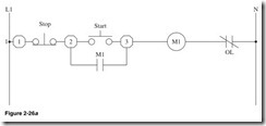
Shown in Fig. 2-26a:
Line 1 Terminal 1, then Normally Closed Stop button, terminal 2 Normally Open Start button. Down one line, Normally Open M1 con- tact. Motor starter M1 with Normally Closed overload contact. When the Start button is pressed, then the M1 motor will be energized and the motor will run until the Stop button is pressed.
The push buttons in Fig. 2-27 can have one Normally Open or one Normally Closed or two Normally Open or two Normally Closed con- tacts. This prevents accidental use of the push button. Typical use is for Stop and Start buttons. For detailed specifications, see Allen Bradley at www.ab.com.
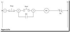
Shown in Fig. 2-27a:
Line 1 Terminal 1, then Normally Closed stop button, terminal 2 Normally Open Start button. Down one line, Normally Open M1 con- tact. Motor starter M1 with Normally Closed overload contact. When the Start button is pressed, then the M1 motor will be energized and the motor will run until the Stop button is pressed.
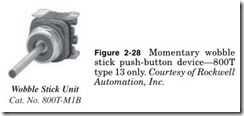
The momentary wobble device in Fig. 2-28 will open a Normally Closed contact and close a Normally Open contact. This operator is available with one Normally Open contact or with one Normally Open and one Normally Closed contact or with two Normally Open and two Normally Closed contacts. For detailed specifications, see Allen Bradley at www.ab.com.
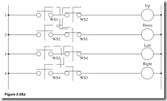
Shown in Fig. 2-28a:
Line 1 Normally Open contact of wobble stick 1, Normally Closed contact of wobble stick 2, up relay.
Line 2 Normally Open contact of wobble stick 2, Normally Closed contact of wobble stick 1, down relay.
Line 3 Normally Open contact of wobble stick 3, Normally Closed contact of wobble stick 4, left relay.
Line 4 Normally Open contact of wobble stick 4, Normally Closed contact of wobble stick 3, right relay
When the up wobble stick 1 is moved, the contact for the up relay will close and the contact for the down relay will open, preventing the up and down relays from being used at the same time.
When the down wobble stick 2 is moved, the contact for the down relay will close and the contact for the up relay will open, preventing the up and down relays from being used at the same time.
When the left wobble stick 3 is moved, the contact for the left relay will close and the contact for the right relay will open, preventing the left and right relays from being used at the same time.
When the right wobble stick 4 is moved, the contact for the right relay will close and the contact for the left relay will open, preventing the left and right relays from being used at the same time.
For detailed specifications on the above items, see the Allen Bradley Catalog at www.ab.com/en/epub/catalogs/12768/229240/ 229244/2531083/tab4.html.

