PLC (PROGRAMMABLE LOGIC CONTROL) CONTROLLERS
The development of programmable logic controllers (PLCs) was driven primarily by the requirements of automobile manufacturers, who constantly changed their production line control systems to accommodate their new car models. In the past, this required extensive rewiring of banks of relays a very expensive procedure. In the 1970s, with the emergence of solid-state electronic logic devices, several automobile companies challenged control manufacturers to develop a means of changing control logic without the need to totally rewire the system. The PLC evolved from this requirement. PLCs are designed to be relatively user-friendly so that electricians can easily make the transition from all-relay control to electronic systems. They give users the capability of displaying and troubleshooting ladder-logic that shows the logic in real time. The ladder-logic can be “rewired” (programmed) and tested, without the need to assemble and rewire banks of relays.
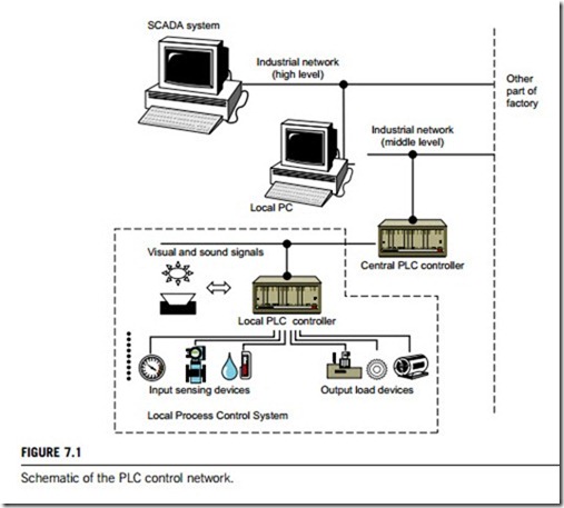
A PLC is a computer with a single mission. It usually lacks a monitor, a keyboard, and a mouse, as normally it is programmed to operate a machine or a system using only one program. The machine or system user rarely, if ever, interacts directly with the program in the PLC. When it is necessary to either edit or create the PLC program, a personal computer is usually (but not always) connected to it. The information from the PLCs can be accessed by supervisory control and data acquisition (SCADA) systems and human machine interfaces (HMIs), to provide a graphical representation of the status of the plant. Figure 7.1 is a schematic of the PLC control network resident in industrial systems.
PLC components and architectures
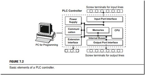
A PLC is actually an industrial microcontroller system (in more recent years we meet microprocessors instead of microcontrollers) with hardware and software that are specifically adapted to the industrial environment. A block schema with the typical components that a PLC consists of is shown in Figure 7.2. Special attention needs to be given to input and output, because most PLC models feature a vast assortment of interchangeable I/O modules that allow for convenient interfacing with virtually
any kind of industrial or laboratory equipment. The program unit is usually a computer used for writing a program (often in a ladder-logic diagram).
(1) Central processing unit (CPU)
This unit contains the “brains” of the PLC, often referred to as a microprocessor or scheduler. The basic instruction set is a high-level program, installed in read-only memory (ROM). The programmed logics are usually stored in electrically erasable permanent read-only memory (EEPROM). The CPU will save everything in memory, even after a power loss. Since it is “electrically erasable”, the logic can be edited or changed as the need arises. The programming device is connected to the CPU whenever the operator needs to monitor, troubleshoot, edit, or program the system, but it is not required during normal operations.
(2) Memory
System memory (today mostly implemented in Flash technology) is used by a PLC as a process control system. Aside from this operating system, it also contains a user program translated from a ladder-logic diagram to binary form. Flash memory contents can be changed only when the user program is being changed. PLC controllers were used before Flash memory, with EPROM instead of Flash memory which needs to be erased with a UV lamp and programmed on programmers. The use of Flash technology has greatly shortened this process and allows reprogramming via a serial cable in an application development program.
User memory is divided into blocks, which have special functions. Some parts are used for storing input and output status. The real status of an input is stored either as “1” or as “0” in a specific memory bit. Each input or output has one corresponding bit in memory. Other parts of the memory are used to store variables in user programs, for example, timer value or counter value.
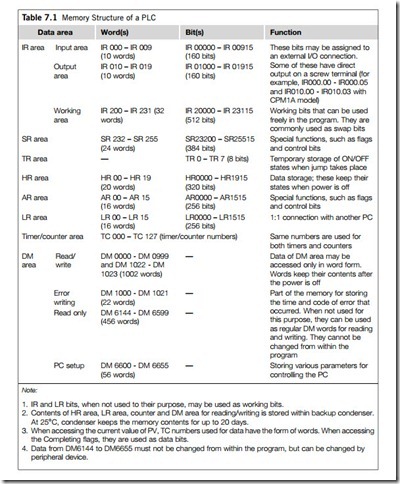
PLC controller memory consists of several areas, as given in Table 7.1, some of which have predefined functions.
(3) Communication board
Every brand of PLC has its own programming hardware, such as a small hand-held device, which resembles an oversized calculator with a liquid crystal display (LCD) but most commonly this is computer-based. Computer-based programmers typically use a special communication board, installed in an industrial terminal or personal computer, which runs the appropriate software program. This allows offline programming, where program logic is developed separately, then loaded onto the CPU when required.
Programming can be done directly into the CPU if desired; in which case, a programmer can test the system, and watch the logic operate as each element is highlighted in sequence on a cathode ray tube (CRT) when the system is running. Since a PLC can operate without having the programming device attached, one device can be used to service many separate PLC systems.
(4) PLC controller inputs
The intelligence of an automated system depends largely on the ability of a PLC controller to read signals from different types of sensors and input devices. Keys, keyboards, and functional switches are the basis of the human machine relationship. On the other hand, to detect a working piece, view a mechanism in motion, or check pressure or fluid level specific automatic devices such as proximity sensors, marginal switches, photoelectric sensors, level sensors, and so on are needed. Thus, input signals can be logical (ON/OFF) or analog in order to receive input from these devices. Smaller PLC controllers usually have digital input lines only while larger ones also accept analog inputs through special units. One of the most frequent analog signals is a current signal of 4 20 mA and a millivolt voltage signal generated by the various sensors that are usually used as inputs for PLCs. You can obtain sensors for different purposes.
Other devices also can serve as inputs to the PLC controller, such as intelligent devices such as robots, video systems, and so forth (a robot, for instance, can send a signal to PLC controller input as information when it has finished moving an object from one place to the other).
(5) PLC controller output
An industrial control system is incomplete if it is not connected to some output devices. Some of the most frequently used devices are motors, solenoids, relays, indicators and sound emitters. By starting a motor, or a relay, the PLC can manage or control a simple system, such as a system for sorting products, or even complex systems such as a service system for positioning the head of a robotic machine. Output can be analog or digital. A digital output signal works as a switch; it connects and disconnects lines. Analog output is continous, and used to generate an analog signal (for instance, a motor whose speed is controlled by a voltage, the value of which corresponds to a desired speed).
(6) Extension lines
Every PLC controller has a limited number of input/output lines, which can be increased by using extension lines, which can be applied to both input and output lines. Also, extension modules can have inputs and outputs that are different from those on the PLC controller (for instance, if relay outputs are on a controller, transistor outputs can be on an extension module). The PLC has input and output lines through which it is connected to a system it directs.
262 CHAPTER 7 Industrial intelligent controllers
Two terms frequently mentioned when discussing connections to inputs or outputs are “sinking” and “sourcing”; both are very important in connecting a PLC correctly to the external environment. The briefest definition of these two concepts would be:
Hence the (þ) and the (-) in the above definition, which refer to the poles of a DC supply. Inputs and outputs that are either sinking or sourcing can conduct electricity only in one direction, so they are only supplied with direct current. According to what we have discussed so far, each input or output has its own return line, so five inputs would need 10 screw terminals on a PLC controller housing. Instead, we use a system of connecting several inputs to one return line as illustrated in Figure 7.2. These common lines are usually marked “COMM” on the PLC controller housing.
(7) Power supply
Most PLC controllers work either at 24 V DC or 220 V AC. On some PLC controllers, usually the bigger ones, you will find the electrical supply as a separate module while small and medium series already contain the supply module. Different types of modules use different amounts of electrical current so the user determine the correct setting.
This electrical supply is not usually used to start external inputs or outputs. The user has to provide separate supplies in starting PLC controller inputs or outputs to ensure a so-called pure supply for the PLC controller. By pure supply we mean a supply where the industrial environment cannot affect it adversely. Some of the smaller PLC controllers supply their inputs with voltage from a small supply source already incorporated into the PLC.
The internal logic and communication circuitry usually operates on 5 or 15 V DC power. The power supply provides filtering and isolation of the low-voltage power from the AC power line. Power supply assemblies may be separate modules, or in some cases plug-in modules in the I/O racks. Separate control transformers are often used to isolate inputs and CPU from output devices. The purpose is to isolate this sensitive circuitry from transient disturbances produced by any highly inductive output devices.
(8) Timers and counters
Timers and counters are indispensable in PLC programming for numbering products, determining the time for a required action, and so on. Timing functions are very important, and cycle periods are critical in many processes.
There are two types of timers; delay-off and delay-on. The first has a delay before turn off and the second has a delay before turning on in relation to the activation signal. An example of a delay-off timer would be staircase lighting, which simply turns off a few minutes after its activation. Each timer has a time basis, or more precisely has several time bases. Typical values are 1, 0.1, and 0.01 second. If the programmer has entered 0.1 as the time basis and 50 as the delay increase number, the timer will have a delay of 5 seconds (50 x 0.1 seconds ¼ 5 seconds).
Timers also have to have the SV value the number of increments that the timer has to calculate before it changes the output status in advance, either as a constant or a variable. If a variable is used, the timer will use a real-time value of the variable to determine a delay. This enables delays to vary depending on the conditions of the process. An example is a system that produces two different products, each requiring different timing during the process itself. Product A requires a period of 10 seconds, so number 10 would be assigned to the variable. When product B appears, the variable can change to that required by product B.
Typically, timers have two inputs. The first is the timer-enable, or conditional input (when this input is activated, the timer will start counting), and the second input is a reset input. This input has to be in OFF status in order for a timer to be active. Some PLC models require this input to be low for a timer to be active; other makers require high status (all of them function in the same way basically). However, if a reset line changes status, the timer erases accumulated value.
PLC control mechanism
A programmable logic controller is a digital electronic device that uses programmable memory to store instructions, and a CPU to implement specific functions such as logic, sequence, timing, counting, and arithmetic, in order to control machines and processes. Figure 7.2 shows a simple schematic of a typical programmable logic controller. When running, the CPU scans the memory continuously from top to bottom, and left to right, checking every input, output, and instruction in sequence. The scan time depends upon the size and complexity of the program, and the number and type of I/O, and may be as short as a few milliseconds, so producing tens of scans per second. This short time makes the operation appear as instantaneous, but one must consider the scan sequence when handling critically timed operations and sealing circuits. Complex systems may use interlocked multiple CPUs to minimize total scan time.
The input and output modules allow the PLC to communicate with the machine and are quite different to those in a PC. The inputs may come from limit switches, proximity sensors, temperature sensors, and so on. The PLC will set the outputs on the basis of the software program and the combination of inputs . These outputs may control motor speed and direction, actuate valves, open or close gates, and control all the motions and activities of the machine.
(1) System address
The key to getting comfortable with any PLC is to understand the total addressing system. We have to connect our discrete inputs, push-buttons, limit-switches, and so on, to our controller, interface those points with the “electronic ladder-logic diagram” (program), and then bring the results out through another interface to operate motor starters, solenoids, lights, and so forth.
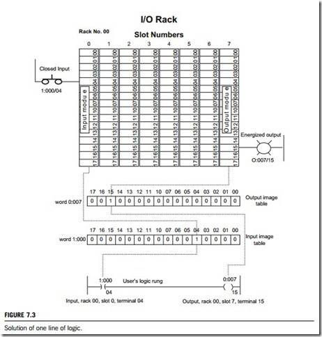
Inputs and outputs are wired to interface modules, installed in an I/O rack. Each rack has a two- digit address, each slot has its own address, and each terminal point is numbered. Figure 7.3 shows a PLC product in which all of these addresses are octal.
We combine the addresses to form a number that identifies each input and output.
Some manufacturers use decimal addresses, and some older systems are based on 8-bit words, rather than 16. There are a number of proprietary programmable controllers for specific applications, such as elevator controls or energy management, which may not follow the expected pattern, but they will use either 8- or 16-bit word structures. It is very important to identify the addressing system before you attempt to work on any system that uses a programmable controller, because one must know the purpose of each I/O bit before manipulating them in memory.
Figure 7.3 shows a very simple line of logic, where a push-button is used to turn on a lamp. The push-button and lamp “hardwiring” terminates at I/O terminals, and the logic is carried out in software. We have a push-button, wired to an input module (I), installed in rack 00, slot 0, and terminal 04. The address becomes I:000/04. An indicating lamp is wired to an output module (O), installed in rack 00, slot 7, and terminal 15. The address becomes O:007/15. Our input address, I:000/04, becomes memory address I:000/04, and the output address 0:007/15 becomes memory address 0:007/15.
In other words, the type of module, the rack address, and the slot position identifies the word address in memory. The terminal number identifies the bit number.
(3) Image table addresses
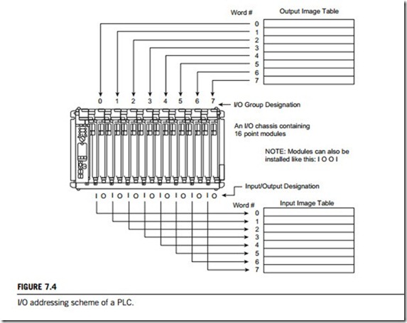
An output image table is reserved in its IR area of the memory (see Table 7.1) as File format, and an input image table is reserved in the same way. A File in memory contains any number of words. Files are separated by type, according to their functions. In the same way, an input image table is also reserved in its IR area of the memory (See Table 7.1) in file format. Figure 7.4 illustrates the respective mapping relationship of the I/O modules to both output and input image tables.
(4) Scanning
As the scan reads the input image table, it notes the condition of every input, and then scans the logic diagram, updating all references to the inputs. After the logic is updated, the scanner resets the output image table, to activate the required outputs. Figure 7.4 shows some optional I/O arrangements and addressing.
In Figure 7.3, we show how one line of logic would perform when the input at I:000/04 is energized: it immediately sets input image table bit I:000/04 true (ON). The scanner senses this change of state, and makes the element I:000/04 true in our logic diagram. Bit 0:007/15 is turned on by the logic. The scanner sets 0:007/15 true in the output image table, and then updates the output 0:007/15 to turn the lamp on.
PLC programming
Programmable logic controllers use a variety of software programming languages. These include sequential function chart (SFC), function block diagram (FBD), ladder-logic diagram (LD), structured text (ST), instruction list (IL), relay ladder logic (RLL), flow chart, C, Cþþ, and Basic. Among these languages, the ladder diagram is the most popular. Almost every language possesses various useful options, such as forced switching on and off of the system inputs/outputs (I/O lines), program follow- up in real time, or documenting a diagram very necessary to understand and to define failures and malfunctions. The programmer can add remarks, names of input or output devices, and comments that can be useful when finding errors, or with system maintenance. Adding comments and remarks enables any technician (and not just the person who developed the system) to understand a ladder-logic diagram easily. Comments and remarks can even precisely quote part numbers in case replacements are needed which speeds up repair of any problems arising because of faulty parts. Formerly, only the person who developed the system had access to the program, so nobody apart from them could understand how it was done. A correctly documented ladder-logic diagram allows any technician to understand thoroughly how the system functions.
(1) Relay ladder logic
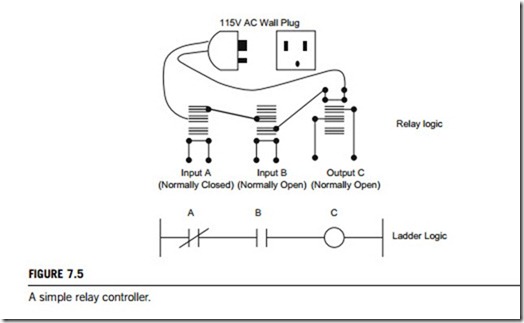
Ladder logic, developed to mimic relay logic, is the main programming method used for PLCs. Relays are used to let one power source close a switch for another (often high current) power source, while keeping them isolated. An example of a relay in a simple control application is shown in Figure 7.5. In this system, the first relay (on the left) is normally closed and will allow current to flow until a voltage is applied to input A. The second relay is normally open and will not allow current to flow until a voltage is applied to input B. If current is flowing through the first two relays, then current will flow through the coil in the third relay, and close the switch for output C. This circuit would normally be drawn in the ladder logic form. This can be read logically as C will be on if A is off and B is on.
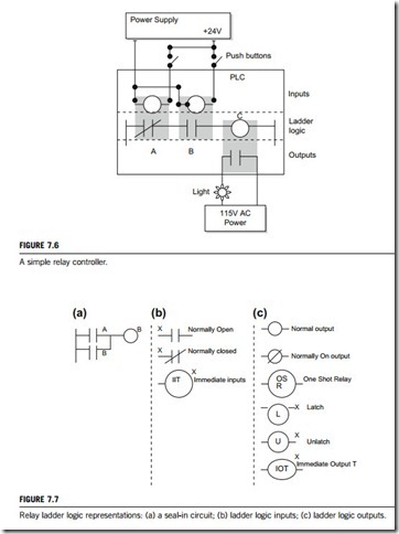
The example in Figure 7.5 does not show the entire control system, but only its logic. Figure 7.6 shows a more complete representation of the PLC. Here there are two inputs from push-buttons and the input, output and logic are all shown.
We can imagine the inputs as activating 24 V DC relay coils in the PLC. This in turn drives an output relay that switches 115 V AC, which will turn on a light. Note; in actual PLCs inputs are never relays, but often outputs are. The ladder logic in the PLC is actually a computer program that the user can enter and change. Note that both of the input push-buttons are normally open, but the ladder logic
inside the PLC has one normally open contact and one normally closed. Do not think that the ladder logic in the PLC needs to match the inputs or outputs. Many beginners will get caught trying to make the ladder logic match the input types.
Many relays also have multiple outputs (throws) and this allows an output relay to also be an input simultaneously. The circuit shown in Figure 7.7(a) is an example of this; it is called a seal in circuit. Here, the current can flow through either branch of the circuit, through the contacts labeled A or B. The input B will only be on when the output B is on. If B is off, and A is energized, then B will turn on. If B turns on then the input B will turn on and keep output B on even if input A goes off. After B is turned on the output, B will not turn off.
PLC inputs are easily represented in ladder logic. Figure 7.7(b) shows the three types of inputs. The first two are normally open and closed inputs, discussed previously. Normally open: an active input X will close the contact and allow power to flow. Normally closed: power flows when the input X is not open. The IIT (Immediate Input Terminal) function allows inputs to be read after the input scan, while the ladder logic is being scanned. This allows ladder logic to examine input values more often than once every cycle. Immediate inputs will take current values, but not those from the previous input scan.
In ladder logic, there are multiple types of outputs, but these are not consistently available on all PLCs. Some will be externally connected, as may the internal memory locations in the PLC. Six types of outputs are shown in Figure 7.7(c). The first is a normal output; when energized it will turn on and energize an output. The circle with a diagonal line through it is a normally on output. When it is energized, the output will turn off. This type of output is not available on all PLC types. When initially energized, the OSR (one-shot relay) instruction will turn on for one scan, but then be off for all scans after, until it is turned off. The L (latch) and U (unlatch) instructions can be used to lock outputs on. When an L output is energized, the output will turn on indefinitely, even when the output coil is
deenergized. The output can only be turned off using a U output. The last instruction is the IOT (Immediate Output Terminal) that will allow outputs to be updated without having to wait for the ladder logic scan to be completed. When power is applied (ON) the output X is activated for the left output, but turned off for the output on the right. An input transition on will cause the output X to go on for one scan (this is also known as a one-shot relay). When the L is energized, this X will be toggled on, and will stay on until the U coil is energized. This is like a flip-flop and stays set even when the PLC is turned off. In some PLCs, all immediate outputs do not wait for the program scan to end before setting an output.
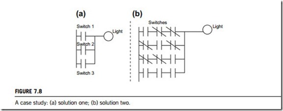
For example, to develop (without looking at the solution) a relay-based controller that will allow three switches in a room to control a single light, there are two possible approaches. The first assumes that if any switch is on will be on the light, but all three switches must be off for the light to be off. Figure 7.8(a) displays the ladder logic solution for this. The second solution assumes that each switch can turn the light on or off, regardless of the states of the other switches. This method is more complex and involves thinking through all of the possible combinations of switch positions. This problem can be recognized as an Exclusive OR problem from Figure 7.8(b).
(2) Programming
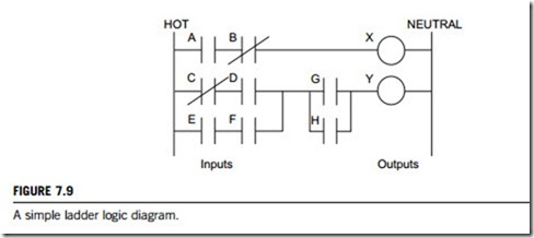
An example of ladder logic can be seen in Figure 7.9. To interpret this diagram, imagine that the power is on the vertical line on the left-hand side; we call this the hot rail. On the right-hand side is the neutral rail. In this figure there are two rungs, and on each rung there are combinations of inputs (two vertical lines) and outputs (circles). If the inputs are opened or closed in the right combination, then the power can flow from the hot rail, through the inputs, to power the outputs, and finally to the neutral rail. An input can come from a sensor or a switch. An output will be some device outside the PLC that is switched ON or OFF, such as lights or motors. In the top rung the contacts are normally open and normally closed, which means if input A is ON and input B is OFF, then power will flow through the output and activate it. Any other combination of input values will result in the output X being off.
The second rung of Figure 7.9 is more complex; several combinations of inputs will result in the output Y turning on. On the left-most part of the rung, power could flow through the top if C is OFF and D is ON. Power could also (and simultaneously) flow through the bottom if both E and F are true. This
would get power half way across the rung, and then if G or H is true the power will be delivered to output Y.
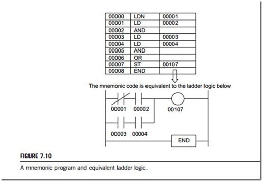
There are other methods for programming PLCs. One of the earliest techniques involved mnemonic instructions. These instructions can be derived directly from ladder-logic diagrams and entered into the PLC through a simple programming terminal. An example of mnemonics is shown in Figure 7.10. In this example, the instructions are read one line at a time from top to bottom. The first line 00000 has the instruction LDN (input load and not) for input 00001. This will examine the input to the PLC, and if it is OFF it will remember a 1 (or true); if it is ON it will remember a 0 (or false). The
next line uses an LD (input load) statement to look at the input. If the input is OFF it remembers a 0; if the input is ON it remembers a 1 (note: this is the reverse of the LD). The AND statement recalls the last two numbers remembered and if they are both true the result is a 1; otherwise the result is a 0. This result now replaces the two numbers that were recalled, so only one number is remembered. The process is repeated for lines 00003 and 00004, but when these are done there are now three numbers remembered. The oldest number is from the AND; the newer numbers are from the two LD instructions. The AND in line 00005 combines the results from the last LD instructions leaving two numbers in memory. The OR instruction takes the two numbers now remaining, and if either one is a 1 the result is a 1; otherwise the result is a 0 giving a final single number output. The last instruction is the ST (store output) that will look at the last value stored and if it is 1, the output will be turned on; if it is 0 the output will be turned off.
The ladder logic program in Figure 7.10 is equivalent to the mnemonic program. Ladder logic will be converted to mnemonic form before being used by the PLC. Mnemonic programming was common in the past, but now it is rarely seen.
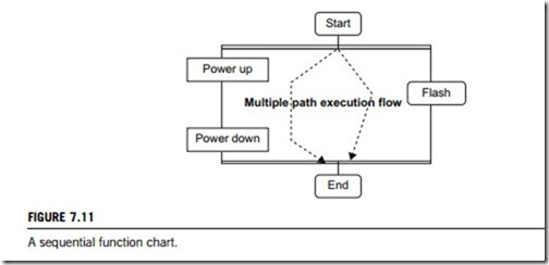
Sequential function charts have been developed to accommodate the programming of more advanced systems. These are similar to flowcharts, but much more powerful. The example seen in Figure 7.11 is doing two different things. To read the chart, start at the top where it says Start. Below this there is the double horizontal line that says follow both paths. As a result, the PLC will start to follow the branch on the left- and right-hand sides separately and simultaneously. On the left there are two functions; firstly a power-up function which will run until it decides it is done, and the power-down function will come after. On the right-hand side is the flash function; this will run until it is done. These functions look unexplained, but each function, such as power-up, will be a small ladder logic program. This method is very different from flowcharts because it does not have to follow a single path through the flowchart.
(3) Ladder diagram instructions
Ladder logic input contacts and output coils allow simple logical decisions. Instructions extend this to allow other types of control. Most of the instructions will use PLC memory locations to get and store values, and track instruction status. Most instructions will normally become active when the input is
true. Some instructions, such as TOF timers, can remain active when the input is off. Other instructions will only operate when the input goes from false to true; this is known as positive edge-triggered. Consider a counter that only counts when the input goes from false to true; the length of time that the input stays true does not change the instruction behavior. A negative edge-triggered instruction would be triggered when the input goes from true to false. These are rarer; unless stated, assume instructions are not edge-triggered.
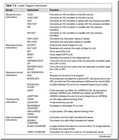
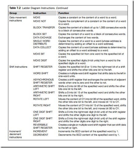
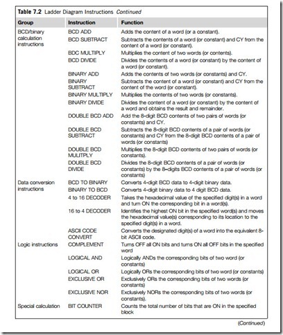
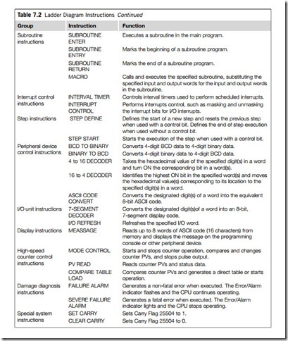
Instructions may be divided into several basic groups according to their operation. Each of these instruction groups is briefly introduced in Table 7.2.
Basic types and important data
Programmable logic controller I/O channel specifications include total number of points, number of inputs and outputs, ability to expand, and maximum number of channels. Number of points is the sum of the inputs and the outputs. A PLC may have any possible combination of these values. Expandable units may be stacked or linked together to increase total control capacity. Maximum number of channels refers to the maximum total number of input and output channels in an expanded system. PLC system specifications to be considered include scan time, number of instructions, data memory, and program memory. Scan time is the time required by the PLC to check the states of its inputs and outputs. Instructions are standard operations (such as mathematical functions) available to PLC software. Data memory is the capacity for data storage. Program memory is the capacity for control software storage. Available inputs for programmable logic controllers include DC, AC, analog, thermocouple, RTD, frequency or pulse, transistor, and interrupt inputs. Outputs for PLC include DC, AC, relay, analog, frequency or pulse, transistor, and triac. Programming options for PLC include front panel, hand held, and computer.
Programmable logic controllers can also be specified with a number of computer interface options, network specifications, and features. PLC power options, mounting options, and environmental operating conditions also important need to be considered.
PLCs are usually one of three general types:
(1) Embedded
The embedded controllers expand their field bus terminals and transform them into a modular PLC. All support the same communication standard such as Ethernet TCP/IP. PCs and compact operating units belonging to the PLC product spectrum are also identical for all controllers.
(2) PC-based
This type of PLC is a slide-in card for a PC that extends every PC or IPC and transforms it into a fully fledged PLC. In the PC, the slide-in card needs only one PCI bus slot and runs fully independently of the operating system. PC system crashes leave the machine control completely cold.
(3) Compact
The compact PLC controller unites the functions of an operating unit and a PLC. To some extent, the compact controller already features integrated digital and analog inputs and outputs. Further field bus terminals in compact PLCs can be connected via an electrically isolated interface such as CANopen.
