FLC (FUZZY LOGIC CONTROL) CONTROLLERS
The aim of this section is to introduce fuzzy logic control technologies and controllers, which include the concepts of fuzzy logic mathematics, the structures of fuzzy control systems, the methodologies of fuzzy control modeling, the types of fuzzy controllers, and the examples of fuzzy control applications, etc. This section emphasizes fuzzy control principles, methodologies, and system controllers.
Fuzzy control principles
An intelligent control system is one in which a physical system or a mathematical model is controlled by a combination of a knowledge-based, approximate (humanlike) reasoning, and/or a learning process structured in a hierarchical fashion. Under this simple definition, any control system which involves fuzzy logic, neural networks, expert learning schemes, genetic algorithms, genetic programming or any combination of these would be designated as intelligent control.
The term “fuzzy” refers to the ability to deal with imprecise or vague inputs. Instead of using complex mathematical equations, fuzzy logic uses linguistic descriptions to define the relationship between the input information and the output action. In engineering systems, fuzzy logic provides a convenient and user-friendly front-end for developing control programs, helping designers to concentrate on the functional objectives, not on the mathematics. Their basic concepts are listed below.
(1) Logical inference
Reasoning makes a connection between cause and effect, or a condition and a consequence. Reasoning can be expressed by a logical inference, or by the evaluation of inputs to draw a conclusion. We usually follow rules of inference that have the form: IF cause1 ¼ A and cause2 ¼ B THEN effect ¼ C, where A, B, and C are linguistic variables. For example, IF “room temperature” is Medium THEN “set fan speed to Fast”, where the Medium is a function defining degrees of room temperature, while Fast is a function defining degrees of speed. The intelligence lies in associating those two terms by means of an inference expressed in heuristic IF . . . THEN terms. To convert a linguistic term into a computa- tional framework, one needs to use the fundamentals of set theory. For the statement IF “room temperature” is Medium, we have to ask and check the question “Is the room temperature Medium?” Boolean logic, has two answers: YES or NO. Therefore, the idea of membership of an element x in a set A is a function mA(x) whose value indicates whether that element belongs to the set A. Boolean logic would indicate, for example, that if mA(x) ¼ 1, then the element belongs to set A, and if mA(x) ¼
0, the element does not belong to set A.
(2) Fuzzy sets
A fuzzy set is represented by a membership function that is defined in the universe of discourse, which gives the grade, or degree, of membership within the set, of any given element. The membership function maps the elements of the universe onto numerical values between 0 and 1. A value of zero implies that the corresponding element is definitely not an element of the fuzzy set, and corresponds to the Boolean value, 0, whilst a value of unity means that the element fully belongs to the set and corresponds to the Boolean value of 1. A value of membership between zero and unity corresponds to fuzzy, or partial membership of the set. In crisp set theory, if someone is taller than 1.8 meters, we can state that such a person belongs to the “set of tall people”. However, such a sharp change from the 1.7999 meters of a “short person” to the 1.8001 meters of a “tall person” not a common sense distinction.
As another example, suppose a highway has a speed limit of 65 miles/hour. Those who drive faster than 65 miles/hour belong to the set A, whose elements are violators, and their membership function has the value of 1. Those who drive slower than the limit do not belong to set A. Is sharp transition between membership and non-membership realistic? Should there be a traffic summons issued to drivers who are caught at 65.5 miles/hour? Or at 65.9 miles/hour? In practical situations there is always a natural fuzzification, where statements are analyzed, and a smooth membership curve usually better describes the degree to which an element belongs to a set.
(3) Fuzzification
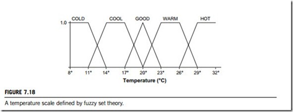
Fuzzification is the process of decomposing a system input and/or output into one or more fuzzy sets. Many types of curves and tables can be used, but triangular or trapezoidal-shaped membership functions are the most common, since they are easier to represent in embedded controllers. Figure 7.18 shows a system of fuzzy sets for an input with trapezoidal and triangular membership functions. Each fuzzy set spans a region of input (or output) values graphed against membership. Any particular input is interpreted from this fuzzy set, and a degree of membership is obtained. The membership functions should overlap, in order to allow smooth mapping of the system. The process of fuzzification allows the system inputs and outputs to be expressed in linguistic terms to allow rules to be applied in a simple manner to express a complex system.
Consider a simplified implementation of an air-conditioning system with a temperature sensor. The
temperature might be read by a microprocessor that has a fuzzy algorithm that processes output to continuously control the speed of a motor which keeps the room at a “good temperature”; it also can direct a vent upward or downward as necessary. Figure 7.18 illustrates the process of fuzzification of the air temperature.
There are five fuzzy sets for temperature: COLD, COOL, GOOD, WARM, and HOT.
The membership function for fuzzy sets COOL and WARM are trapezoidal, the membership function for GOOD is triangular, and those for COLD and HOT are half triangular, with shoulders
indicating the physical limits for such a process (staying in a place with a room temperature lower than 8oC or above 32oC would be quite uncomfortable). The way to design such fuzzy sets depends solely on the designer’s experience and intuition. The figure shows some non-overlapping fuzzy sets, which can indicate any nonlinearity in the modeling process. There an input temperature of 18oC would be considered COOL to a degree of 0.75 and would be considered GOOD to a degree of 0.25. To build the rules that will control the air-conditioning motor, we could watch how a human expert adjusts the settings to speed up and slow down the motor in accordance with the temperature, obtaining the rules empirically. For instance, if the room temperature is good, keep the motor speed medium; if it is warm, turn the knob of the speed to fast, and blast the speed if the room is hot. On the other hand, if the temperature is cool, slow down the speed, and stop the motor if it is cold. The beauty of fuzzy logic is the way it turns common sense, and linguistic descriptions, into a computer-controlled sys- tem. To complete this process it is necessary to understand how to use some logical operations to build the rules.
Boolean logic operations must be extended in fuzzy logic to manage the notion of partial truth truth-values between “completely true” and “completely false”. A fuzziness nature of a statement such as “X is LOW” might be combined with the fuzziness statement of “Y is HIGH” and a typical logical operation could be given as X is LOW AND Y is HIGH. What is the truth-value of this AND operation? Logic operations with fuzzy sets are performed with the membership functions. Although there are various other interpretations for fuzzy logic operations, the following definitions are very convenient in embedded control applications:
After fuzzy reasoning, we have a linguistic output variable that needs to be translated into a crisp value. The objective is to derive a single crisp numeric value that best represents the inferred fuzzy values of the linguistic output variable. Defuzzification is such an inverse transformation, which maps the output from the fuzzy domain back into the crisp domain. Some defuzzification methods tend to produce an integral output, by considering all the elements of the resulting fuzzy set with their corresponding weights. Other methods take into account just the elements corresponding to the maximum points of the resulting membership functions. The following defuzzification methods are of practical importance:
(a) Centre-of-Area (C-o-A). The C-o-A method is often referred to as the Centre-of-Gravity method because it computes the centroid of the composite area representing the output fuzzy term.
(b) Centre-of-Maximum (C-o-M). In the C-o-M method only the peaks of the membership functions are used. The defuzzified, crisp, compromise value is determined by finding the place where the weights are balanced. Thus, the areas of the membership functions play no role, and only the maxima (singleton memberships) are used. The crisp output is computed as a weighted mean of the term membership maxima, weighted by the inference results.
(c) Mean-of-Maximum (M-o-M). The M-o-M is used only in cases where the C-o-M approach does not work. This occurs whenever the maxima of the membership functions are not unique and the question is which one of the equal choices one should take.
Fuzzy control strategies are derived from experience and experiment rather than from mathematical models and, therefore, linguistic implementations are accomplished much faster. They involve a large number of inputs, most of which are relevant only for some special conditions. Such inputs are activated only when the related condition prevails. In this way, little additional computational overhead is required for adding extra rules, and the resulting, rule-based structure remains understandable, leading to efficient coding and system documentation. In modern industries, are adaptive fuzzy control and fuzzy supervisory control, by applied wide in both process control and production automation.
(1) Adaptive fuzzy control
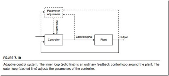
An adaptive controller in industrial applications can be defined as a controller with adjustable parameters and a mechanism for adjusting them. Despite the lack of a formal definition, an adaptive fuzzy controller has a distinct architecture, consisting of two loops; a control loop and a parameter adjustment loop (Figure 7.19).
Systems with a dominant time delay are notoriously difficult to control, and the fuzzy self- organizing controller was developed specifically to cope with dead time. To the inventors it was a further development of the original fuzzy controller. Today it may be classified as a model- reference adaptive system, an adaptive system in which the performance specifications are given by a reference model. In general the model returns the desired response to a command signal. The parameters are changed according to the model error, the deviation of the plant response from the desired response. It is still a challenge to design the adjustment mechanism such that the closed-loop system remains stable.
(2) Fuzzy supervisory control
In industrial applications, a supervisory system can be defined as a system that evaluates whether local controllers satisfy prespecified performance criteria, diagnoses causes of deviation from these criteria, plans actions, and executes the planned actions.
By process control we shall understand the automation of a large-scale industrial plant, where its complexity makes it impossible to achieve the complete satisfaction of a particular control specification. Typical goals for a supervisory controller are safe operation, highest product quality, and most
economic operation. All three goals are usually impossible to achieve simultaneously, so they must be prioritized; presumably, safety gets the highest priority.
Fuzzy control modeling
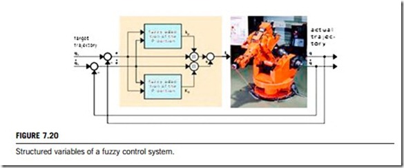
Although the development of fuzzy control strategies comes from experience and experiments rather than from mathematical models, the conventional control approach requires modeling of the physical reality. Basically, there is simply a “language difference” between fuzzy and conventional control; differential equations are the language of conventional control, and rules are the language of fuzzy control. To clearly explain this difference, a robot control system is shown in Figure 7.20. In this figure, the fuzzy control variables make it possible to design, optimize and implement tailor- made (i.e. heuristically based, nonlinear) dream controls with specific parameters and boundary conditions. Compared with conventional control concepts, the implementation of fuzzy control requires relatively little effort and is quite transparent from an engineering point of view. Utilization of fuzzy logic as a design and optimization tool has therefore proven useful in industrial control systems.
Basically, then, the role of modeling in fuzzy control design is quite similar to its role in conventional control system design. In the former there is a focus on the use of rules to represent how to control the plant rather than differential equations. From a theoretical point of view, fuzzy logics are rule-based, or use knowledge that can be used to identify both a model, as a universal approximation, as well as a nonlinear controller. The most relevant information about any system comes from either a mathematical model, sensory input/output data, or human expert knowledge. The common factor in all these three sources is knowledge.
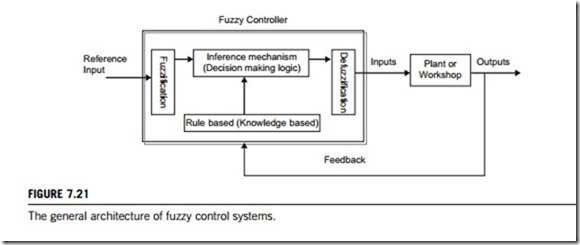
Both fuzzy control system design and fuzzy controller design essentially amount to (1) choosing
the fuzzy controller inputs and outputs, (2) choosing the preprocessing that is needed for the controller inputs and possibly postprocessing that is needed for the outputs, and (3) designing each of the four components of the fuzzy controller, as shown in Figure 7.21. Accordingly, in industrial control, the three methods below may be used for fuzzy control modeling.
(1) Experimental method
By experimenting and determining how the process reacts to various inputs, one can characterize an input-output table. Graphically the method is equivalent to plotting some discrete points on an input- output curve, using the horizontal axis for input and the vertical axis for output. These are disad- vantages to this approach; the process equipment may not be available for experimentation, the procedure could be very costly, and for a large number of input values it is impractical to measure the output, and interpolation between measured outputs would be required. One must also be careful to determine the expected ranges of inputs and outputs to make sure that they fall within the range of the measuring instruments available.
(2) Mathematical modeling
Control engineering requires an idealized mathematical model of the controlled process, usually in the form of differential or difference equations. Laplace transforms and z-transforms are respectively used. In order to make mathematical models simple enough, certain assumptions are made, one of which is
that the process is linear, that is, its output is proportional to the input. Linear techniques are valuable because they provide good insight, and since no general theory for the analytic solution of nonlinear differential equations exists, these are no comprehensive analysis tools for nonlinear dynamic systems. Another assumption is that the process parameters do not change over time (that is, the system is time- invariant) despite system component deterioration and environmental changes. Other problems arising when developing a meaningful and realistic mathematical description of an industrial process are;
(1) poorly understood phenomena, (2) inaccurate values of various parameters, (3) model complexity.
(3) Heuristic method
The heuristic method consists of modeling and understanding in accordance with previous experience, rules-of-thumb and often-used strategies. A heuristic rule has the logical form: IF <condition> THEN
<consequence>, or in a typical control situation; IF <condition> THEN <action>. Rules associate conclusions with conditions. The heuristic method is therefore similar to the experimental method of constructing a table of inputs and corresponding output values where instead of having crisp numeric values of input and output variables, one uses fuzzy values: IF input-voltage ¼ Large THEN output- voltage ¼ Medium. The advantages are: (1) the assumption of linearity is not required, and (2) heuristic rules can be integrated into the control strategies of human operators.
As discussed in subsection 7.3.1, there are standard choices for fuzzification and defuzzification interfaces. Designer inference mechanisms may have their preferred and may use this for many different processes. Hence, the main design work is to define the rule-base, which is constructed so that it represents a human expert “in-the-loop”. The information that is loaded into the rules may come from an actual human expert who has learned how best to control the plant (or workshop) processes. In other situations there may be no such human expert, and the control engineer will simply study the plant process (perhaps using modeling and simulation) and write down a set of control rules derived from observations.
As an example, in cruise control, it is clear that anyone who has experience of driving a car can practice regulating the speed about a desired set-point and load this information into a rule-base. One rule that a human driver may use is “If the speed is lower than the set-point, then press down further on the accelerator pedal”. A rule representing more detailed information about how to regulate the speed would be “If the speed is lower than the set-point AND it is rapidly approaching the set-point, then release the accelerator pedal by a small amount”. This second rule characterizes our knowledge about how to make sure that we do not overshoot our desired goal (the set-point speed). Generally speaking, very detailed expertise in the rule-base results in better performance.
At this point we will examine how to use fuzzy systems for estimation and identification to study the problem of how to construct a fuzzy system from numerical data, and how to construct a fuzzy system that will serve as a parameter estimator.
To design fuzzy control systems or controllers in a plant, we need data-fitting technology that shows roughly how the input-output mapping of the estimator should behave. One way to generate this is to use a simulation test platform. A set of simulations can then be conducted, each with a different value for the parameter to be estimated. Appropriate data pairs can be gathered, that allow for the construction of a fuzzy estimator. For some plants it may be possible to perform this procedure with actual experimental data (by physically adjusting the parameter to be estimated). In a similar way, one could construct fuzzy predictors by using the basic function identification and approximation.
Some fundamental issues now need to be considered, including fitting a function to input-output data, incorporating linguistic information into the function to match it to the data measuring a function fits the data; and how to choose a data set for an engine failure estimation problem (a type of parameter estimation problem in which when estimates of the parameters take on certain values).
The main identification and estimation methods are:
1. The least squares method, which is for tuning fuzzy systems and training fuzzy systems.
2. The gradient method, which can be used to train a standard fuzzy system, especially a standard Takagi-Sugeno fuzzy system.
3. The clustering method, which contains two techniques for training fuzzy systems based on
clustering.
4. Hybrid methods for training fuzzy systems can be developed by combining the above methods.
The first technique uses “c-means clustering” and least squares to train the premises and consequents, respectively, of the Takagi-Sugeno fuzzy system; while the second uses a nearest-neighborhood technique to train standard fuzzy systems. Most work in fuzzy control has to date focused only on its advantages and has not considered possible disadvantages it (the reader should therfore be cautious when reading the literature). For example, the following questions may need examining when gath- ering heuristic control knowledge:
1. Will the behaviors that are observed by a human expert and used to construct the fuzzy controller include all situations that can occur due to disturbances, noise, or plant parameter variations?
2. Can the human expert realistically and reliably foresee problems that could arise from closed-loop
system instabilities or limit cycles?
3. Will the human expert be able to effectively incorporate stability criteria and performance objectives (e.g., rise-time, overshoot, and tracking specifications) into a rule-base to ensure that reliable operation can be obtained?
Fuzzy industrial controllers
This subsection briefly introduces three important types of fuzzy logic controllers in industrial control applications.
(1) Embedded fuzzy controllers
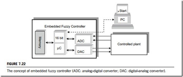
The concept of fuzzy logic makes feasible the use of a fuzzy controller built on a microcontroller or microprocessor chipset or industrial computers. Manufacturers have recognized the power of fuzzy logic and have created fuzzy kernels and support tools. In some industrial applications, such as motion control, electrical drives, temperature and humidity stabilization, the fuzzy controller receives infor- mation from the controlled process via analog-digital converters and controls it through digital-analog converters, as in Figure 7.22.
(2) Fuzzy three-term (PID-like) controllers
The industrial three-term (PID-like) controller constitutes the backbone of industrial control, having been in use for over a century. They can take a number of forms, from the early mechanical to later
hydraulic, pneumatic, analog and digital versions. The modern form takes the form of multitasking discrete-time three-term (PID) algorithms embedded in almost all industrial PLCs and RTUs.
The advent of fuzzy control motivated many researchers to reconsider this controller in the hope that “fuzzification” would improve its domain of effectiveness. This is a case of a technology retrofit, in which computational intelligence is applied to improve a well-known device. The result has been a new generation of intelligent three-term (PID-like) controllers that are more robust. Fuzzy logic can be applied in a number of ways. One obvious approach is to fuzzify the gains of the three-term (PID) controller by establishing rules whereby these gains are varied in accordance with the oper- ating state of the closed system.
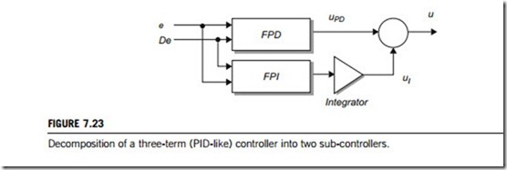
It is often more convenient to partition the three-term controller into two independent fuzzy sub- controllers that separately generate the signals uPD and uI that correspond to the proportional plus derivative term and the integral term respectively. The result is a fuzzy proportional plus derivative sub-controller FPD (fuzzy proportional and differentiate) in parallel with a fuzzy integral controller FPI (fuzzy proportional and integral) as shown in Figure 7.23. Both sub-controllers are fed with the error and its derivative. The second sub-controller requires an integrator (or accumulator) to generate the integral term.
(3) FPGA-based fuzzy logic controllers
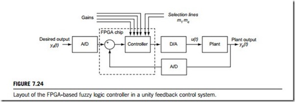
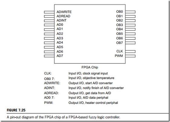
A recent hardware design and implementation of fuzzy logic controllers builds all fuzzy control modules on a field-programmable gate array (FPGA) chipset. The general layout of the controller chip in a unity feedback control system is shown in Figure 7.24. Generally, the proposed controller accepts both the output of the plant (yp) and the desired output (yd), as digital signals, and delivers a digital control action signal as an output. The design also accepts four digital signals that represent the gain coefficients needed by the controller (proportional gain Kp, derivative gain Kd, integral gain Ki, and output gain Ko), and two one-bit signals to select the type of the controller. Figure 7.25 shows a view of its FPGA chipset.
A case study of fuzzy industrial controls
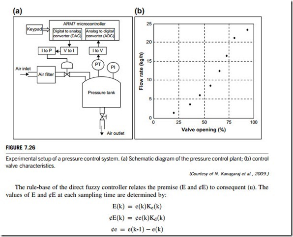
The schematic diagram of a pilot pressure control plant is shown in Figure 7.26(a), where PT denotes pressure transmitter, PI denotes pressure indicator, “V to I” denotes voltage to current converter, “I to V” denotes current to voltage converter, and “I to P” denotes current to pressure converter. It consists of a miniature pressure tank, whose inlet is connected to an air compressor through a 50 mm control valve. At the bottom of the tank, an outlet is provided with a manually operated gate valve to allow air flow at a constant rate. An accurate pressure transmitter connected to the pressure tank is used to measure tank pressure and provide an output current in the range of 4 to 20 mA. In this closed-loop pressure-regulating system, the inlet air flow rate is manipulated by changing the control valve position in such a way as to attain the desired pressure.
An increasing sensitive-type nonlinear electro-pneumatic control valve, whose characteristics can be seen in Figure 7.26(b), is used for inlet flow manipulation. The pressure control system also has a dead time of 1.4 seconds, which has been calculated from an open-loop experiment.
The prime objective of the proposed design is to improve stability and robustness. Industrial pressure plants are usually connected to several parallel operating plants, such as in an industrial steam-generating boiler connected to a steam network of a high-pressure header, intermediate pressure level, and low pressure level. To provide a smooth and trouble-free supply for the steam-consuming processes, pressure should be stabilized at close to the set level. In addition, industrial pressure plants may be exposed to frequent load changes caused by the trips and start-ups of the steam-consuming processes. To overcome such load disturbances, and to stabilize the output over the input variations,
the controller needs an online tuning method. Hence, the supervisory-system-based online tuning method to improve the stability and robustness of the controller is emphasized in its design.
The control structure consists of a simple, upper-level, rule-based, (supervisory) controller and a lower-level, rule-based, (direct) fuzzy controller. A standard type fuzzy logic controller has been applied in both upper and lower levels of this hierarchical control structure. The supervisory fuzzy system determines the scaling factor for the direct fuzzy controller at each sampling time by evaluating the inputs e(k) and u(k).
(1) The direct fuzzy controller
The design of the direct fuzzy controller is based on research into this process and underlying domain knowledge about pressure tank systems. The universe of discourse of each input and output are divided into adjacent intervals with overlap. The membership functions are introduced to characterize each interval, and, using fuzzy logic, a continuous input and output mapping is made. The universe of discourse of inputs and output are determined from the operating range of the process. Values are finely tuned by experiment to improve controller performance. In the case of the direct fuzzy controller, five membership triangular functions with 50% overlap have been chosen for the inputs E, ¢E, and output (u). The linguistic descriptions of input membership functions are NB (negative big), NS (negative small), ZE (zero), PS (positive small) and PB (positive big). The output membership functions are VS (very small), SM (small), MD (medium), HI (high), and VH (very high).
where E and ¢E are the error and change in error inputs of the direct fuzzy controller with scaling factor taken into account, Ke and Kd are the scaling factors, ¢e is the change in error, and k represents the sampling instant. The structure of the control rules of the direct fuzzy controller with two inputs and an output is expressed as: “If E is PS and ¢E is NS, then u is MD.”
(2) Supervisory fuzzy controller
The rule-based supervisory fuzzy controller is designed to tune the input scaling factor of the direct fuzzy controller in a closed-loop system. The online scaling factor modification is adapted in the proposed control scheme, thus enhancing controller performance and significantly reducing the need for human intervention in real industrial control applications. The universe of discourse of input and output of the supervisory fuzzy controller is based on the maximum allowable range of the process. Three, triangle-shaped, membership functions are used for both the inputs and outputs. The membership function of input e is denoted by NE (negative), ZE (zero), and PE (positive); the input u and outputs Ke and Kd are denoted by LOW (low), MED (medium), and HIG (high).
The rule-base of the supervisory fuzzy controller has been designed in the light of operative knowledge about the process. A typical fuzzy control rule of the proposed supervisory system is expressed as: “If e is NE and u is MED; then Ke is LOW and Kd is HIG”.
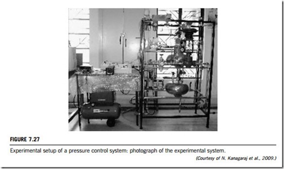
This proposed fuzzy control scheme has been tested for a real-time pressure control application using an ARM7-based embedded microcontroller board. ARM7 is a 32-bit advanced reduced in- struction set computing (RISC) architecture processor, having one megabyte (MB) on-board flash memory, network application capable processor (NACP) features, RS-232 trans-receiver and onboard analog-to-digital converter (ADC) and digital-to-analog converter (DAC) for real-time interfacing. A photograph of the ARM7 embedded microcontroller board and the experimental set-up is shown in Figure 7.27.
