THYRISTORS
Many industrial switching circuits are implemented with MOSFETs designed for high voltage and high power. You will sometimes hear these devices called insulated gate field-effect transistors (IGFETs).
Other power-switching devices are also widely used, especially thyristors. A thyristor is a semiconductor device used for switching purposes in industrial control. Like the relay, it is used to apply and control electrical power to motors, heating elements, lights, and other loads in industrial applications. In many applications, thyristors replace relays. A thyristor acts as a switch, but because of its solid-state nature, is far faster in switching than a relay. There are three basic types of thyristors: silicon-controlled rectifiers (SCRs), triacs, and diacs.
Silicon-Controlled Rectifier
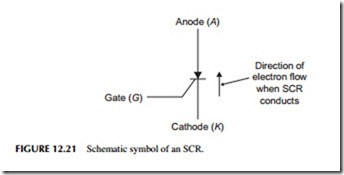
The SCR is a three-terminal thyristor that acts like a silicon rectifier diode whose conductor is controlled by an input current. The schematic symbol for an SCR is shown in Figure 12.21 . The symbol is similar to that of a diode with a cathode and an anode. Note that the third element of the SCR is known as the gate. The SCR will conduct current between cathode and anode, but only if the proper control current is applied to the gate. The gate must be made positive with respect to the cathode in order for the SCR to conduct. When conducting, the SCR acts like a closed switch. The voltage drop across the cathode and anode will be approximately 0.7 to 1.8 volts, depending on the size of the SCR and how much current is flowing through it. When the cathode and anode are reverse biased, current will not flow through the device.
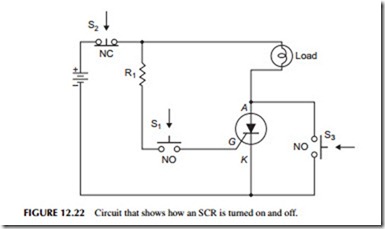
Thyristors, like relays, are generally used to control a larger current with a smaller current. Figure 12.22 shows how an SCR is used as a switch to apply DC power to a light bulb. The load could also be a motor or heating element. The DC voltage is connected so that the cathode and anode of the SCR are forward biased, but no current will flow through the device until a current is applied to the gate. This is done with the switch S1 . With the switch open, no current flows in the gate. Closing the switch, however, applies a positive volt- age to the gate through resistor R1. This causes the SCR to turn on. When it conducts, it acts as a low-resistance “on” switch and the light bulb goes on. At this point, switch S1 may be opened. It is not necessary to maintain current in the gate in order for the device to continue to conduct. The gate current only
needs to be momentary, for it is only required to turn the device on. The device remains on like a latching relay that has been pulsed.
The gate element is only used to turn the SCR on. Removing gate current will not turn the device off. To cause the SCR to stop conducting, the circuit must be broken. This can be done with a momentary-contact, normally closed pushbutton, in series with the circuit, like S2 in Figure 12.22. Depressing this pushbutton will break the circuit, stopping the current in the SCR, and the light bulb will go off. To turn the bulb back on, S1 must again be depressed to apply gate current momentarily.
Another way to stop conduction is to momentarily short around the SCR, as shown in Figure 12.15. When switch S3 is closed momentarily, current will flow through it and the bulb, bypassing the SCR. The current in the SCR will drop to zero. When switch S3 is opened, the circuit will be off.
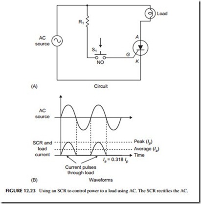
While SCRs are sometimes used to control DC power, in most applications they are used to control AC. Figure 12.23A shows the SCR used to apply AC to a light bulb. If switch S1 is closed, gate current will be applied to the device. The device, however, will only conduct when the anode is made positive with respect to the cathode. This, of course, occurs when the applied AC voltage has the correct polarity. Since the SCR operates as a rectifier diode, current will only flow through the device on the positive half-cycles of the sine wave. The current through the light bulb will be a pulsating DC, as illustrated in Figure 12.23B. The brightness of the lamp will depend on the average amount of current flowing.
The average amount of current through the light bulb, or other load, can be controlled by using the gate element. Various electronic circuits are used to adjust the time when the SCR turns on. By turning on the SCR at the appro- priate time in the positive half-cycle, the duration of the current flow can be controlled. The longer the current is allowed to flow, the higher the average
current in the load. By changing the control point, the brightness of the bulb can be varied.
Diac
A diac is a two-terminal semiconductor device that conducts in either direction when a voltage of a specific level is exceeded. This voltage is called the triggering voltage. Typical diac triggering voltages are in the 20- to 45-volt range. The diac is used as a triggering device for SCR and triacs as it deter- mines when the device will conduct or cut off.
Triac
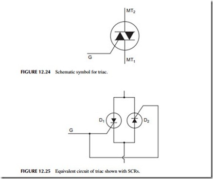
A triac is another three-terminal thyristor. Its operation is similar to that of an SCR, but the triac will conduct in either direction. The schematic symbol for the triac is shown in Figure 12.24. Current will flow from main terminal 1 (MT1)
to main terminal 2 (MT2), or from main terminal 2 (MT2) to main terminal 1 (MT1), depending on the polarity of the voltage applied, and if the gate triggers the device on.
An approximate, equivalent circuit of the triac is shown in Figure 12.25. Here, two SCRs are connected back to back with their gates connected together. Current can flow in either direction, depending on whether D1 or D2 conducts. Of course, SCR conduction depends on whether a gate-triggering current is applied. Triacs, like SCRs, are used primarily to switch AC volt- age to a load. If gate current is applied continuously, the triac will conduct in both forward and backward directions, causing both positive and negative half- cycles of the AC to be applied to a load.
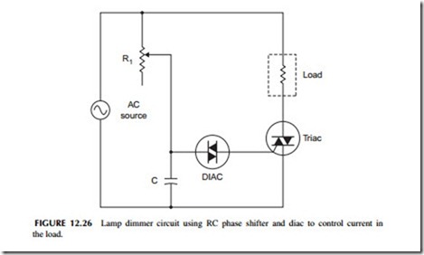
Figure 12.26 shows a circuit used for light-dimming purposes. The load is a light bulb. An RC phase shifter and diac-triggering device are used on the gate of the triac. Assume that the diac has a triggering voltage of 30 volts. If the voltage across the diac is less than 30 volts, it will not conduct. As soon as the 30-volt point is reached or exceeded, the diac rapidly conducts and fires the SCR. Keep in mind that the diac is a bidirectional device, and that current will flow through it in either direction if the bias voltage in either direction exceeds the triggering voltage level.
The triac will conduct on both positive and negative half-cycles of the applied AC. The phase shifter made up of R1 and C will set the triggering delay. It will determine at what point in the AC cycle the diac will fire and apply gate current to the triac. Figure 12.27 shows the waveforms at two different phase-shift points in the circuit. Note that current flows through the load in both the positive and negative half-cycles, but the duration of current flow depends on the point where the gate triggers. In Figure 12.27, the average cur- rent through the load will be relatively high at a 60-degree phase shift, and the bulb will be bright. At 120 degrees, the triggering point is late in each half- cycle, allowing only a small amount of current to flow through the bulb. The bulb, therefore, will glow dimly. Adjusting R1 will allow the brightness of the bulb to be varied from nearly full on to full off. This is the circuit normally used in household and industrial light dimmers.
This same circuit can be used to control the speed of AC motors. In connecting a hand drill as the load, for example, R1 will vary the speed of rotation.
Triacs are also widely used as solid-state relays.
