Inductive reactance is a form of resistance to current flow. Like DC current, alternating current creates a magnetic field around a wire. Alternating current is continually changing in magnitude and polarity. The strength of the magnetic field around a wire changes with the amount of current. The direction of current flow in the wire changes with the polarity of the AC voltage. The polarity of the magnetic field around a wire changes with the polarity of the AC voltage.
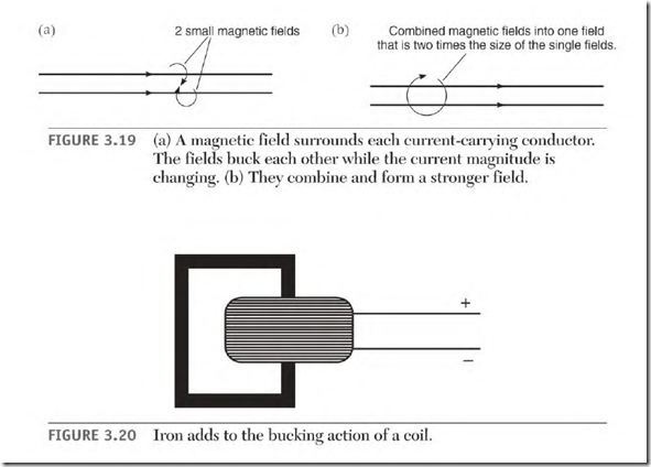
When two wires carrying AC current in the same direction are placed next to each other (Fig. 3.19a), there is a bucking interaction between them until their magnetic fields combine into a larger magnetic field (Fig. 3.19b). This interaction will cause the current to flow out of step with and later than the voltage that drives it. This current delay is called inductance. Resistance to current flow caused by inductance is called inductive reactance.
Inductive reactance occurs when there is a changing magnetism. Inductive reactance can be demonstrated with a length of wire. If the wire is in a straight line, the only significant resistance to AC current flow is the resistance of the wire itself. If the wire is wound into a coil, there will be inductance and inductive reactance (resistance to current flow). If the wire is wound around a loop of iron, as shown in Fig. 3.20, inductive reactance is increased even more.
Impedance
Impedance is the sum of the resistance of the conductor and inductive reactance. Inductive reactance furnishes most of the resistance to current flow in an AC motor.
Inductive Reactance and Counter-voltage
Inductive reactance in the windings of an AC motor serves the same purpose as counter-voltage in the armature of a DC motor. The resistance of the windings of a DC armature and the windings of an AC motor are very low. If DC voltage is applied to an AC winding, there would be no inductive reactance and the winding would be destroyed.
Power Factor
Power factor is defined as the ratio between true power and apparent power. Thue power is the power that is actually used by a load. Apparent power is the sum of the true power amperes and the magnetizing amperes (see the upcoming section “Magnetizing Amperes and Lagging Power Factor”). The power factor of a circuit is found by dividing true power by apparent power.
True power amperes can be found with a wattmeter. The meter’s reading in watts divided by the applied voltage equals the true amperes.
Amperes, read with an AC ammeter, are the circuit’s real power plus its apparent power. A clamp-on AC ammeter displays the sum of the magnetizing amperes plus the true amperes of an inductive circuit. True power amperes of a wattmeter divided by apparent power amperes of an AC ammeter equals the power factor. The result is a decimal value or percentage
A power factor meter can be used to find the power factor of a circuit. It measures both the voltage and amperes, and computes the result.
The power supplier’s watthour meter records and charges for only the real power.
Unity Power Factor
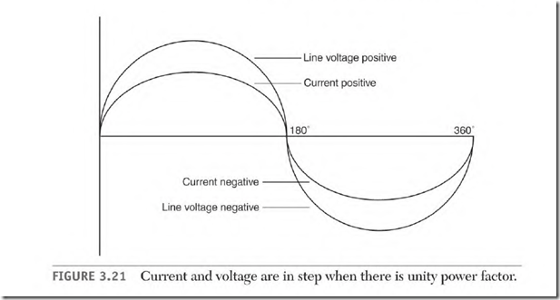
If there is no reactive power, the current and the voltage are in step (Fig. 3.21). The condition is called unity power factor. All the power used at unity power factor is real power and is recorded by the power meter as consumed power. (Power used by resistors or stove elements is at unity power factor.)
Magnetizing Amperes and Lagging Power Factor
When amperes are out of step with the voltage, the circuit has a power factor. The power factor can be leading or lagging. (Leading power factor is covered under “Capacitor Function, ” later in the chapter.) This section explains a lagging power factor and the relationship of current and magnetism in a coil during one cycle.
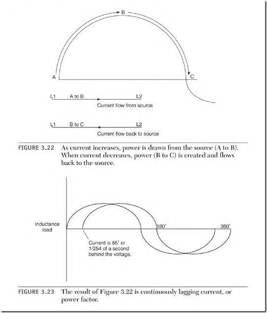
As current flow increases from point A to point B in Fig. 3.22 through a coil of wire, there is a bucking interaction between the magnetic fields of each turn of wire. The magnetic fields of the entire coil then combine to form a large magnetic field. The power source supplies the current needed to magnetize the coil (magnetizing amps) until peak current (point B) is reached. The current at this point starts to drop toward zero. As the current decreases, the magnetic field starts to collapse. The collapsing magnetic lines of force cut the turns of the coil and create a voltage in them. The power this voltage creates makes current (or magnetizing amps) flow back to the power source. The current cycle now crosses the zero line (point C) and flows in the opposite direction. The coil is now being magnetized in the opposite polarity. It will draw power and then send it back to the source in the same sequence as the previous half-cycle. With inductance in the circuit, current is out of step with (lagging) the voltage by a number of degrees (which represent time). (The circuit has a lagging power factor as shown in Fig. 3.23.)
The magnetizing amperes do no work. The more inductive components the circuit has, the higher the magnetizing amperes become. In a circuit with a low power factor, the magnetizing amperes may be more than the real amperes.


