SIMILARITY BETWEEN INDUCTION MOTOR AND TRANSFORMER
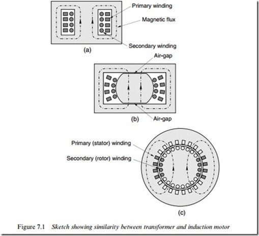
The development of a wound-rotor induction motor from a single-phase transformer is depicted in Figure 7.1.
In Figure 7.1(a), we see a section through one of several possible arrangements of a single-phase iron-cored transformer, with primary and secondary windings wound concentrically on the centre limb. In most transformers there will be many turns on both windings, but for the sake of simplicity only four coils are shown for each winding.
Operation of the transformer is explored in Section 7.3, but here we should recall that the purpose of a transformer is to take in electrical power at one voltage and supply it at a diVerent voltage. When an a.c. supply is connected to the primary winding, a pulsating magnetic Xux (shown by the dotted lines in Figure 7.1) is set up. The pulsating Xux links the secondary winding, inducing a voltage in each turn, so by choosing the number of turns in series the desired output voltage is obtained. Because no mechanical energy conversion is involved there is no need for an air-gap in the magnetic circuit, which therefore has an extremely low reluctance.
In Figure 7.1(b), we see a hypothetical set-up in which two small air- gaps have been introduced into the magnetic circuit to allow for the motion that is essential in the induction motor. Needless to say we would not do this deliberately in a transformer as it would cause an unnecessary increase in the reluctance of the Xux path (though the eVect on performance would be much less than we might fear, as discussed in Section 7.3). The central core and winding space have also been enlarged somewhat (anticipating the need for two more phases), without materi- ally altering the functioning of the transformer.
Finally, in Figure 7.1(c) we see the two sets of coils arranged as they
would be in a 2-pole wound-rotor induction motor with full-pitched coils.
The most important points to note are:
● Flux produced by the stator (primary) winding links the rotor (sec- ondary) winding in much the same way as it did in Figure 7.1(a), i.e. the two windings remain tightly coupled by the magnetic Weld.
● Only one-third of the slots are taken up because the remaining two- thirds will be occupied by the windings of the other two phases: these have been omitted for the sake of clarity.
● The magnetic circuit has two air-gaps, and because of the slots that accommodate the coils, the Xux threads its way down the teeth, so that it not only fully links the aligned winding, but also partially links the other two phase-windings.
● When the rotor turns, the rotor winding also turns and it therefore
links less of the Xux produced by the stator. If the rotor in Figure 7.1(c) turns through 908, there will be no mutual Xux linkage, i.e. the degree to which the two windings are magnetically coupled depends on the rotor position.
If the two windings highlighted in Figure 7.1(c) were used as primary and secondary, this set-up would work perfectly well as a single-phase transformer.
We now turn to the theory of the transformer, to develop its equiva- lent circuit and in so doing lay the foundations for the induction motor equivalent circuit that is our ultimate objective.
