PERFORMANCE PREDICTION – EXAMPLE
The per-phase equivalent circuit parameters (referred to the stator) of a 4-pole, 60 Hz, 440 V three-phase delta-connected induction motor are as follows:
Stator resistance, R1 = 0:2 V Stator and rotor leakage reactances, X1 = X 0 = j1:0 V Rotor resistance, R 0 = 0:3 V Magnetising reactance, Xm = j40 V Iron-loss resistance, Rc ¼ 250 V:
The mechanical frictional losses at normal speed amount to 2.5 kW.
We will calculate the input line current, the output power and the eYciency at the full-load speed of 1728 rev/min.
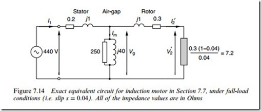
The per-phase equivalent circuit, with all values in Ohms, is shown in Figure 7.14. The synchronous speed is 1800 rev/min and the slip speed is thus 1800-1728 =72 rev/min, giving a slip of 72/1800 = 0.04. The electromechanical resistance of 7:2 V is calculated from the expression
2( (1 – s)=s), with R2 ¼ 0:3 V. Given that the power in this resistor
Stator Air-gap Rotor
represents the mechanical output power, we will see that, as expected, it dominates our calculations.
Although the various calculations in this example are straightforward, they are not for the faint-hearted as they inevitably involve frequent manipulation of complex numbers, so most of the routine calculations will be omitted and we will concentrate on the results and their inter- pretation.
Line current
To Wnd the line current we must Wnd the eVective impedance looking in from the supply, so we Wrst Wnd the impedances of the rotor branch and the magnetising (air-gap) branches. Expressed in ‘real and imaginary’ and also ‘modulus and argument’ form these are:
Rotor branch impedance, Magnetising branch impedance, Zm The parallel combination of these two branches has an eVective imped- ance of 6:74 þ j2:12 or 7:07ff17:5o. At roughly 7 V, and predominantly
resistive, this is in line with what we would expect: the magnetising branch impedance is so much higher than the rotor branch that the latter remains
dominant. We must now add the stator impedance of 0:2 þ j1 to yield the total motor impedance per phase as The motor is mesh connected so the phase voltage is equal to the line voltage, i.e. 440 V. We will use the phase voltage as the reference for angles, so the phase current is given by
Output power
The output power is the power converted to mechanical form, i.e. the power in the Wctitious load resistance of 7.2 V, so we must Wrst Wnd the current through it.
The input current I1 divides between the rotor and magnetising branches according to the expressions
Again we see that these currents line up with our expectations. Most of the input current Xows in the rotor branch, which is predominantly resistive and the phase-lag is small; conversely relatively little current Xows in the magnetising branch and its large phase-lag is to be expected from its predominantly inductive nature.
The power in the load resistor is given by
three phases so the total mechanical power developed is 62.96 kW.
The generated torque follows by dividing the power by the speed in rad/s, yielding torque as 348 Nm, or 116 Nm/phase.
We are told that the windage and friction power is 2.5 kW, so the useful output power is 62:96-2:5 ¼ 60:46 kW.
Efficiency
We can proceed in two alternative ways, so we will do both to act as a check. Firstly, we will Wnd the total loss per phase by summing the powers in the winding resistances and the iron-loss resistor in Figure 7.14.
The losses in the two winding resistances are easy to Wnd because we already know the currents through both of them: the losses are W/phase for the stator and rotor, respectively.
The iron loss is a bit more tricky, as Wrst we need to Wnd the voltage (Vm) across the magnetising branch (sometimes called the gap voltage, Vg, as in Figure 7.14). We can get this from the product of the rotor current and the rotor impedance, which yields The power in the 250 V iron-loss resistor is now given by (408:5)2= 250 ¼ 667 W/phase. The total loss (including the windage and friction) is then given by
Alternatively we could have found the input power directly from the known input voltage and current, using Pin ¼ 3(V1I1 cos f1) ¼ 3 x 440 x 57:82 x cos 24:3o ¼ 69:59 kW, which agrees with the result above.
Phasor diagram
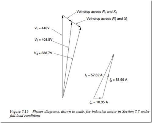
It is instructive to Wnish by looking at the phasor diagrams showing the principal voltages and currents under full-load conditions, as shown in Figure 7.15, which is drawn to scale.
From the voltage phasor diagram, we note that in this motor the voltdrop due to the stator leakage reactance and resistance is signiWcant, in that the input voltage of 440 V is reduced to 408.5 V, i.e. a reduction of just over 7%.
The voltage across the magnetising branch determines the magnetis- ing current and hence the air-gap Xux density, so in this motor the air- gap Xux density will fall by about 7% between no-load and full-load. (At no-load the slip is very small and the impedance of the rotor branch is high, so that there is negligible rotor current and very little volt-drop due
to the stator impedance, leaving almost the full 440 V across the mag- netising branch.)
A similar volt-drop occurs across the rotor impedance, leaving just under 390 V applied at the eVective load. Note, however, that because the stator and rotor impedances are predominantly reactive, the appre- ciable volt-drops are not responsible for corresponding power losses.
These signiWcant volt-drops reXect the fact that this motor is suitable
for direct-on-line starting from a comparatively weak supply, where it is important to limit the starting current. The designer has therefore deliberately made the leakage reactances higher than they would other- wise be in order to limit the current when the motor is switched on.
To estimate the starting current we ignore the magnetising branch and put the slip s ¼ 1, in which case the rotor branch impedance becomes 0:3 þ j1, so that the total impedance is 0:5 þ j2 or 2.06 V. When the full voltage is applied the phase current will be 440/2:06 ¼ 214 A. The full-load current is 57.8 A, so the starting current is 3.7 times the full-load current. This relatively modest ratio is required where the supply system is weak: a stiV supply might be happy with a ratio of 5 or 6.
We have already seen that the torque is directly proportional to the power into the rotor, so it should be clear that when we limit the starting current to ease the burden on the supply, the starting torque is unavoidably reduced. This is discussed further in the following section.
The current phasor diagram underlines the fact that when the motor is at full-load, the magnetising current is only a small fraction of the total. The total current lags the supply voltage by 24.38, so the full-load power-factor is cos 24.38 = 0.91, i.e. very satisfactory.


