Carburetor Service
It is beyond the scope of this book to provide an exhaustive treatise on the overhaul procedures of the hundreds of carburetors in use. Although there are perhaps two dozen basic carburetor designs in use in recent years, each one has many models and each model requires individual ad justment specifications. Therefore, to provide the reader with a working knowledge of what it takes to be a carburetor specialist, we shall outline in a general way the requirements of carburetor ser vicing, including the overhaul procedure on a popular model of a Carter, Ford, Holley, Roches ter and Stromberg carburetor.
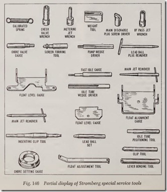
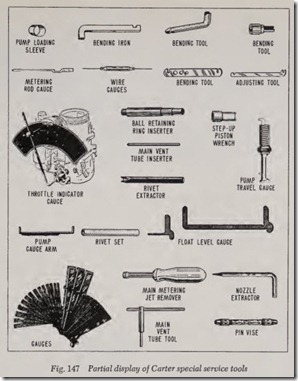
There are a number of special tools which one must have available for accurate and efficient carburetor rebuilding. Figs. 146 and 147 show the t ools a carburetor specialist uses in serviCmg Stromberg and Carter carburetors. If the reader ·doubts the valu e of these tools , let him pick up an old junk carbur etor and take it apart to see how far one can go before being stopped for the want of one of those special tools. Even if most of the work could be done without a n umber of these t ools, very likely a lot of time would be lost and more important, an accur ate and efficient job would not be produc ed.
Therefore, in the following pages, we shall con fine our discussion to carbur etor service tips, the procedure for rebuildin g a few popular carburet ors, and the adjustments which must be made pr ecisely in order for the carburetor to function as it was intended.
SERVICE TIPS
1. Dirt is th e great enemy of good carburetion.
It not only fills up air and fuel passages, but it also accelerates the wear of delicate parts. Therefore, make sure that the work bench, hands, tools and all parts are absolutely clean.
2. To prevent the entrance of dirt while the carburetor is off the engine, tape the opening in the manifold.
3. When disassembling a carburetor, it is a good idea to group the parts as they come out of each assembly. An inexpensive muffin pan which can accommodate six muffins is an ideal container to keep the parts of the various sys tems of the carburetor together.
4. Rap screws and jets with a light hammer and screwdriver to loosen them. Forcing tight fit-ting parts with a screwdriver will burr the slots and make it difficult to install them.
5. After all parts have been disassembled, clean the castings and all parts thoroughly with an approved carburetor cleaner and remove any gaskets that may have been overlooked in the disassembly.
6. Use cleaning solutions and compressed air for cleaning holes in carburetors. Acids, wires, sandpaper or drills may do damage beyond repair.
7. Before ordering parts, make a careful list of the parts needed. On the average, a carburetor repair kit contains all the parts required for rebuilding a carburetor. It includes a full set of gaskets, needle valve and seat assembly, bowl cover fuel strainer, all jets, metering rods (Carter), throttle connector rod, accelerating pump plunger, pump check valves, and vari ous other items which experience dictates should be replaced on a particular carburetor model. There may be a part or two of im proved design to correct some small fault.
8. After obtaining the correct repair kit, empty the package and substitute each new part for the old one which is in the cups of the muffin pan. As each part is substituted, discard the old one to avoid the possibility of mixing the new with the old.
9. Soak new gaskets in kerosene (never plain water). Dry gaskets may not seal or they may crack.
10. Soak pump pistons in kerosene before using.
Never use a screwdriver or a knife to insert the piston in the pump cylinder as damage to the plunger leather may result. Instead, use a suitable loading sleeve.
11. Make sure all jets, screws, and seats are firmly tightened, and that gaskets (when called for) are under these parts.
12. Assemble parts so they fit freely and operate smoothly. Do not force as the parts may not work afterward.
13. All carburetor linkages such as connector rods, fast idle linkages, etc., should not be lubri cated as the increased accumulation of dirt and grit this will cause will promote wear.
CLEANING PARTS
Regardless of the number of new parts that are used in rebuilding a carburetor, the job in the end will not be satisfactory unless all metal parts are thoroughly cleaned. Because of the nature of car buretor parts, with numerous small passages sub ject to fouling with tenacious carbon and gum deposits, ordinary cleaning processes are entirely inadequate. The correct procedure is to use a cleaning bath in which metal parts can be im mersed and “soaked” for sufficient time after dis assembly to thoroughly clean all surfaces and passages.
There are several preparations which have beendeveloped especially for cleaning carburetors. Re gardless of the cleaning material used, however, be sure to rinse the parts thoroughly in kerosene
or white gasoline to remove all gummy deposits that have been softened by the cleaner. Blow out all passages in castings with compressed air and blow off all parts so they are free of solvent.
Do not soak cork, plastic or leather parts in the cleaner. Wipe such parts with a clean cloth.
Remove all carbon from barrels of the body flange so that the throttle valves may close prop erly. Be sure to clean all carbon out of the idle ports.
CARTER BBS OVERHAUL
This type carburetor is used on Chrysler Corp. six-cylinder engines. The BBS denotes that the unit is a Ball and Ball single barrel carburetor. The two barrel counterpart is the BBD carburetor.
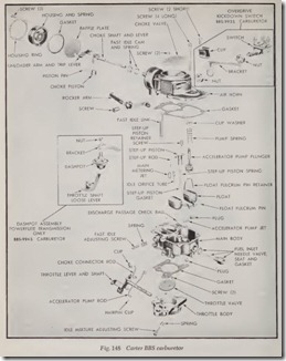
The procedure which follows applies in general to all models of this type carburetor but to avoid confusion in the reader’s mind, specifically it refers to a single model. Bear in mind also that the adjustment specifications given apply only to the particular model carburetor under discussion. Fig. 148 shows an exploded view of the BBS version.
Carburetor Disassemble
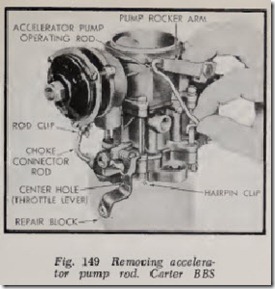
1. Remove choke connector rod and accelerator pump operating rod, Fig. 149.
2. Remove air hom attaching screws and care fully lift straight up to remove air horn as sembly. Discard the gasket. Long screws at tach throttle body to main body. Use care to prevent accidental damage to throttle body.
3. Disengage accelerator pump plunger from rocker arm by pushing up on bottom of plunger and sliding it off the hook, Fig. 150.
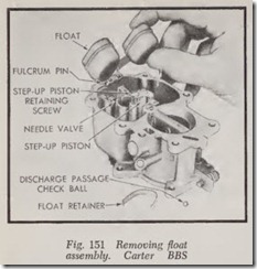
4. Remove float pin retainer, float pin and float, Fig.151.
5. Remove step-up piston, spring, step-up rod, main metering jet and gasket, and idle orifice tube, Fig. 152.
6. Remove accelerator pump discharge check ball.
To remove the pump jet, first remove jet plug.
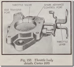
7. Remove idle adjustment screw and spring from throttle body. Fig. 153 shows details of throttle body.
Carburetor Assemble
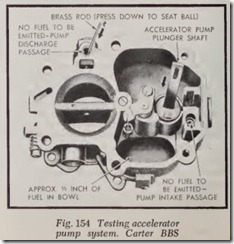
Testing Accelerator Pump System-Install the plunger in the cylinder and the discharge check ball on its seat. Pour a small quantity of gasoline in the bowl. Move the plunger up and down
slowly several times to expel all air from the pump passage. Hold the ball down firmly with a brass rod and raise the plunger, Fig. 154. Press the plunger down. No fuel should flow from the pump inlet or discharge passage. If gasoline is evident from either point, clean the passages again and repeat tests. If leakage is still evident, replace the check ball.
Main Body-Install the accelerator pump jet and plug. Install idle orifice tube and tighten securely. Install main metering jet and gasket. Tighten securely. Install step-up piston spring and step-up rod. See Fig. 152 and carefully guide step-up rod into main metering jet. Place float assem bly and inlet needle valve in position.
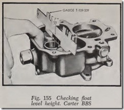
Checking Float Level-Seat needle with finger pressed against float lip. There should be 7/32″ from top of crown of each float to the top of the main body, Fig. 155. Each float must be adjusted for this setting. It is important that the floats do not touch the sides of the bowl.
Air Horn and Throttle Body-Place a new gasket on throttle body and position main body, making sure they are aligned. Assemble pump plunger, spring and cup washer and insert through air horn, engaging pump arm. Place a new gasket on main body and position air horn. Install attaching screws and tighten securely. At tach choke connector rod and accelerator pump operating rod.
Adjustments
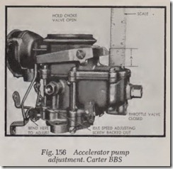
Accelerator Pump-Back out throttle adjusting screw and open the choke valve so that the throt tle valve can be completely seated in the carbu retor bore. The adjustment is made with the pump connector rod in the center hole of the throttle lever. With the throttle valve closed, measure the distance between the top of the float bowl cover to the end of the plunger shaft, marked “A” in Fig.156. This dimension varies according to the par ticular carburetor. If necessary, carefully bend the connector rod at the lower angle to obtain the desired result.
Fast Idle and Unloader-Remove thermostatic coil housing, gasket and baffie plate. Back out throttle adjusting screw. Open throttle valve par tially and hold choke valve in fully closed posi tion. Then close throttle valve. This procedure will allow fast idle cam to revolve to fast idle position. Measure the clearance between the throttle valve and bore of carburetor on the side opposite the idle port, Fig. 157. The clearance varies between one model carburetor and another. This clearance can be adjusted by bending the choke connector rod at the lower angle.
The unloader adjustment must be made af ter the fast idle adjustment has been performed. Hold the th rottle valve wide open and close the choke valve as far as possible without forcing. Clearance is measured between the upper edge of the choke valve and the inner wall of the carburetor air horn, Fig. 158. This clearance dimension also varies according to carburetor model. To obtain the correct adjustment, bend the arm on the choke trip lever.
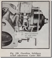
Overdrive Kickdown Switch-Open the throttle valve to wide open position and adjust the hex nuts on the switch to have 1/64 to 3/64″ clearance between the kickdown switch lever and the switch stem guide, Fig. 159.
Powerflite Dashpot-Maximum dashpot action is obtained by loosening the lock nut and adjust ing the unit so that the dashpot plunger shaft can be moved inwardly approximately 3/32″ when the throttle valve is tightly closed, Fig. 160. After ad justment is made, tighten lock nut.
