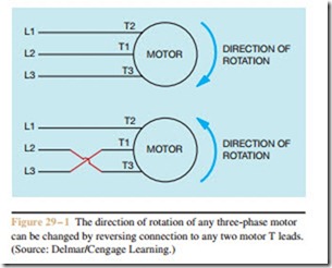
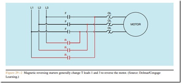
The direction of rotation of any three-phase motor can be reversed by changing any two motor T leads L1 (Figure 29–1). Since the motor is connected to the power line regardless of which direction it operates, a separate contactor is needed for each direction. If the L3 reversing starters adhere to NEMA standards, T leads 1 and 3 will be changed (Figure 29–2). Since only one motor is in operation, however, only one overload relay L1 is needed to protect the motor. True reversing controllers contain two separate contactors and one over-load relay. Some reversing starters will use one separate contactor and a starter with a built-in overload relay.
Others use two separate contactors and a separate over- load relay. A vertical reversing starter with overload re- lay is shown in Figure 29–3, and a horizontal reversing starter without overload relay is shown in Figure 29–4.
Interlocking prevents some action from taking place until some other action has been performed. In the case of reversing starters, interlocking is used to prevent
both contactors from being energized at the same time. This would result in two of the three phase lines being shorted together. Interlocking forces one contactor to be de-energized before the other one can be energized. There are three methods that can be employed to assure interlocking. Many reversing controls use all three.
Mechanical Interlocking
Most reversing controllers contain mechanical interlocks as well as electrical interlocks. Mechanical interlocking is accomplished by using the contactors to operate a mechanical lever that prevents the other contactor from closing while one is energized. Mechanical interlocks are supplied by the manufacturer and are built into reversing starters. In a schematic diagram, mechanical interlocks are shown as dashed lines from each coil joining at a solid line (Figure 29–5).
Electrical Interlocking
Two methods of electrical interlocking are avail- able. One method is accomplished with the use of double acting push buttons (Figure 29–6). The dashed lines drawn between the push buttons indicate that they are mechanically connected. Both push buttons will pushed at the same time. The normally closed part of the FORWARD push button is connected in series with R coil, and the normally closed part of the REVERSE push button is connected in series with F coil. If the motor should be running in the forward direction and the REVERSE push button is pressed, the normally closed part of the push button will open and disconnect F coil from the line before the normally open part closes to energize R coil. The normally closed section of either push button has the same effect on the circuit as pressing the STOP button.
The second method of electrical interlocking is accomplished by connecting the normally closed auxiliary contacts on one contactor in series with the coil of the other contactor (Figure 29–7). Assume that the FORWARD push button is pressed and F coil energizes. This causes all F contacts to change position. The three F load contacts close and connect the motor to the line. The normally open F auxiliary contact closes to maintain the circuit when the FORWARD push button is released, and the normally closed F auxiliary contact connected in series with R coil opens (Figure 29–8).
If the opposite direction of rotation is desired, the STOP button must be pressed first. If the REVERSE push button were to be pressed first, the now open F auxiliary contact connected in series with R coil would prevent a complete circuit from being established. Once the STOP button has been pressed, however, F coil de-energizes and all F contacts return to their normal position. The REVERSE push button can now be pressed to energize R coil (Figure 29–9). When R coil energizes, all R contacts change position. The three R load contacts close and connect the motor to the line. Notice, however, that two of the motor T leads are connected to different lines. The normally closed R auxiliary contact opens to prevent the possibility of F coil being energized until R coil is de-energized.

