Socket Circuits
Socket outlets provide an easy and convenient method by which portable appliances may be connected to the electrical supply. Each appliance is equipped with a plug and a flexible cord which for safety reasons should not be longer than two metres. The plug is pressed into the socket outlet thereby connecting the appliance to the supply.
There are two types of socket outlet allowed by the ETCI Rules, for general indoor purposes. One of these, the most commonly used type, is the 13 A flat pin manufactured to IS 411 and BS 1363 standards. The other type is the 16 A two pin side earth socket, often referred to as the continental type.
Both types are available in flush and surface formats with or without an integral switch. They are designed to fit the standard single and twin socket boxes. These boxes are approximately 30 mm deep to accommodate the number and diameter of the cables which may have to be connected to the sockets.
![]()
![]()
![]() Socket outlets should be mounted at a height between 400 mm and 1200 mm above finished floor level ( FFL ) The standard mounting height is 450 mm to the centre of the socket, except in premises used by the elderly or disabled, where this should be increased to 1100 mm. They should also be at least 100 mm above worktop level.
Socket outlets should be mounted at a height between 400 mm and 1200 mm above finished floor level ( FFL ) The standard mounting height is 450 mm to the centre of the socket, except in premises used by the elderly or disabled, where this should be increased to 1100 mm. They should also be at least 100 mm above worktop level.
Sockets outlets in general must be protected by a Residual Current Device ( RCD ) having a sensitivity ( tripping current ) not exceeding 30 mA.
To avoid the possibility of loss of supply to a freezer when the RCD trips due to a fault on a socket circuit, the freezer may be connected as follows:
1. A fixed outlet from a circuit not protected by an RCD.
2. A dedicated socket-outlet circuit protected by its own separate RCD.
The 13 A plug and socket arrangement incorporates a number of safety features:
· The plug is fused and therefore offers better protection for the flexible cord to which it is attached. ( Fuse rating should match current rating of flexible cord ).
· The live and neutral pins of the plug are insulated for part of their length to avoid the possiblity of them being touched while plugging in or out.
· It is not possible to insert a plug so that a pin protrudes from the socket.
· The socket apertures are shuttered to prevent say, a child inserting small metallic objects, thereby receiving an electric shock. ( Some manufacturers are providing interlocked shutters on the live and neutral apertures ).
Since the plug is fused it is possible to supply a relatively large number of sockets from one circuit, as protection is only required for the circuit conductors. Because all socket outlets will not be in use at the same time and the majority of them will be used to supply small loads such as table lamps, television, stereos, radios, etc. sockets should be installed as much for convenience as to supply specific appliances.
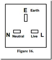
The polarity of the socket must be as shown in Figure 16 when viewed from the front. The terminals are marked L, N and E on the rear of the socket.
Radial Final Circuit
In a radial final circuit supplying sockets, each socket outlet is fed via the previous one. Live is connected to live, neutral to neutral and earth to earth at each socket outlet. The cable used must be at least 2.5 mm2, and the maximum number of socket outlets per circuit is ten. The radial final circuit should not supply more than two rooms. A kitchen should be supplied by at least two radial circuits. The fuse or MCB size fitted to a radial final circuit should be a maximum of 20 A for 2.5 mm2 conductors. Figure 18 shows a block diagram for a radial final circuit supplying socket outlets.
It is recommended that twin socket outlets be installed rather than single types as the initial cost is low in relation to having them replaced at a later date. This also helps avoid the use of double adaptors which are prone to overheating problems.
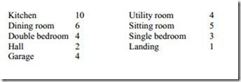
The following are guidelines as to the recommended number of socket outlets per location in a typical domestic dwelling:
The Ring Final Circuit
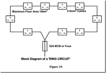
Ring final circuits supplying sockets are very similar to radial final circuits, in that each socket outlet is fed from the previous one, but in ring final circuits the last socket is returned to the same three terminals in the distribution board.
N.B. The same three terminals means, that the two ends of each conductor ( LNE ) must be clamped under the same terminal screw.
The cable used must be capable of carrying 0.67 times the rated current of the protective device on the circuit. Normally this is 2.5mm2, which has a current carrying capacity of 23 Amps, when installed in normal domestic situations.
Using the factor of 0.67 we can calculate the maximum load allowed on the circuit. Calculation:- Maximum load on cables 23 / 0.67 = 34.33 Amps.
Alternatively:
Given a protective device current rating, find the minimum Current Carrying Capacity of the cable required
Calculation:- Minimum CCC of cable 32 x 0.67 = 21.44 Amps.
An MCB with a rating of 32 Amps is fitted to ring final circuits in domestic installations. This provides protection for the 2.5 mm2 cables, the calculation is as shown above.
A ring final circuit may supply an unlimited number of socket outlets, provided the area served is not greater than 100 square metres. Ring circuits should not be used in kitchens. If two or more ring circuits are to be installed, the socket outlets should be distributed evenly between them.
A ring final circuit must remain unbroken throughout its length. If the conductors in a ring circuit are cut, then the terminations should be such that the electrical continuity of the ring remains as good, as if they were not cut.
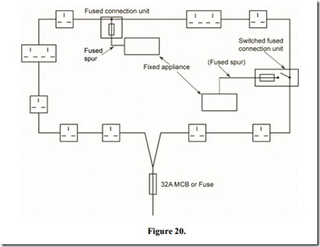
Ring circuits should be planned in such a way that all the outlets are included in the ring. In spite of this, circumstances will arise where it would not be practical to run two cables to a remote outlet. Also, it may be necessary to supply permanently connected appliances. In either case, a spur may be taken from the ring circuit.
A spur is defined as “a branch connection from a ring final circuit”. All spurs must be fused. Spurs are used to supply permanently connected appliances. The fuse in the connection unit should be rated to suit the spur cable, e.g. a 1.5mm2 cable may be protected by a 5 Amp fuse.
Figure 20 shows a typical ring final circuit with spurs connected.


