HIGHWAY ADDRESSABLE REMOTE TRANSDUCER (HART)
HART is an acronym for highway addressable remote transducer, a two-way digital communication interface and protocol which works with 4 20 mA analog signaling. HART is chosen for traditional instrumentation equipment in industrial control systems, in most cases for the field level, and has therefore become one of the most popular industrial communication interfaces and protocols.
Historically, HART was the first implementation of a fieldbus that was developed in the early 1980s by a company named Rosemount Inc. for host management of field devices in process industries. In 1986, it was made an open protocol, then in July of 1993, the HART Communication Foundation was established to provide worldwide support for application of this technology. Nowadays, HART specifications continue to be updated to broaden the range of possible applications. A recent HART development, the device description language (DDL), provides a universal software interface to both new and existing devices.
12.2.1 HART communications
Most industrial control systems have numerous instruments and devices at the field level. While processes are running, the host controller therefore should communicate with these devices in order to
(1) configure or reconfigure them, (2) gather diagnostics, (3) troubleshoot, (4) read additional measurements (5) determine device health and status, etc. A host in the system can either be a network server, a programmable controller, a hand-held communicator, or other device.
There are many benefits to full use of HART communication. Costs can be reduced by improving plant operations and increasing efficiency, and expensive process disruptions and unplanned shut- downs are avoided. Properly utilized, the intelligent capabilities of HART-smart devices can keep plants operating at maximum efficiency. A real-time HART integration with plant control, safety, and asset management systems unlocks the value of connected devices and extends the capability of systems in detecting any problems with the device or its connection to the process, or interference with accurate communication between the device and system.
The world’s leading suppliers of process automation control systems and instrumentation all support HART communication. Most automation system suppliers offer direct HART-enabled I/O and PC-based software applications to leverage the intelligence in HART-smart field instruments or devices for continuous device condition monitoring, real-time diagnostics, and multivariable process information.
(1) HART communication principles
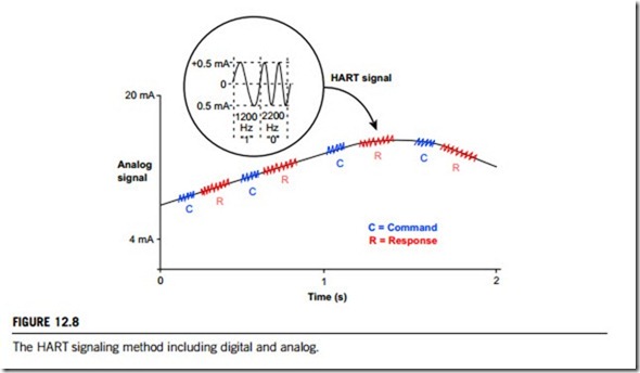
HART communication occurs between two HART-enabled devices, typically a field instrument or device and a control or monitoring system. An analog measurement signal is used to transmit digital information, and an additional signal is modulated to the measurement signal by using the frequency shift keying (FSK) technique. With the FSK, the two frequencies of the additional signal; 1200 and 2200 Hz, to represent the bit values 1 and 0, respectively. This makes it possible to transfer additional information without affecting the analog measurement signal. As indicated by Figure 12.8, HART provides two simultaneous communication channels: the 4 20 mA analog signals and a digital signal. The 4 20 mA signal communicates the primary measured value (in the case of a field instrument or device) using the 4 20 mA current loop, the fastest and most reliable industry standard. Additional
device information is communicated using a digital signal that is superimposed on the analog signal containing information such as device status, diagnostics, additional measured or calculated values. Together, the two communication channels provide a complete field communication solution that is easy to use and configure, is low-cost and is very robust.
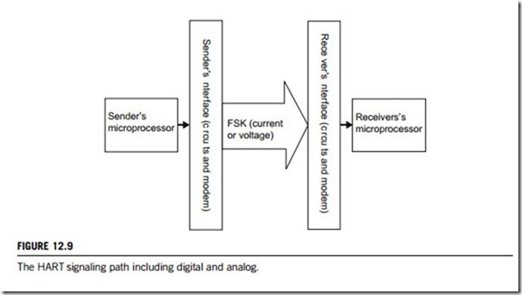
The HART signal path from the microprocessor in a sending device to the microprocessor in a receiving device is displayed in Figure 12.9. Amplifiers, filters, and the network between these two interfaces have been omitted for simplicity. At this level the diagram is the same, regardless of whether a master or slave is transmitting. Notice that, if the signal starts out as a current, the FSK is a voltage, but if it starts out a voltage it stays a voltage.
The transmitting device begins by turning on its carrier and loading the first byte to be transmitted into its interface circuits. It waits for the byte to be transmitted and then loads the next one. This is repeated until all the bytes of the message (these messages are always defined as commands that are of predefined format) are exhausted, then it waits for the last byte to be serialized and finally turns off its carrier. With minor exceptions, the transmitting device does not allow a gap to occur in the serial stream; the start and stop bits are used for synchronization and the parity bit is part of the HART error detection.
The serial character stream is applied to the modulator of the sending modem. The modulator operates such that a logic 1 applied to the input produces a 1200 Hz periodic signal at the modulator output. Logic 0 produces 2200 Hz. The type of modulation used is called continuous phase frequency shift keying (CPFSK). “Continuous phase” means that there is no discontinuity in the modulator output when the frequency changes. When the sender’s interface output (modulator input) switches from logic 1 to logic 0, the frequency changes from 1200 to 2200 Hz with just a change in slope of the transmitted waveform. A moment’s thought reveals that the phase does not change through this transition. Given the chosen shift frequencies and the bit rate, a transition can occur at any phase.
At the receiving end, the demodulator section of a modem in its interface converts FSK back into a serial bit stream at 1200 bps. Each character is converted back into an 8-bit byte and parity is checked. The receiving microprocessor reads the incoming bytes from its interface and checks parity for each one until there are no more, or until parsing of the data stream indicates that this is the last byte of the message. The receiving microprocessor accepts the incoming message only if its amplitude is high enough to cause carrier detect to be asserted. In some cases, the receiving microprocessor will have to test an I/O line to make this determination. In others, the carrier detect signal gates the receive data so that nothing (no transitions) reaches the receiving interface unless carrier detect is asserted.
The HART protocol puts most of the responsibility (such as timing and arbitration) onto the masters. This eases the development of field instrument or device software and puts the complexity into the device that is more suited to deal with it. A master typically sends a command and then expects a reply. A slave waits for a command and then sends a reply. The command and associated reply are called a transaction. There are typically periods of silence (when no device is communicating) between transactions. A slave accesses the network as quickly as possible in response to a master request. Network access by masters requires arbitration, done by observing who sent the last transmission (a slave or the other master) and by using timers to delay their own transmissions. Thus, a master allows time for the other master to start a transmission. The timers constitute dead time when no device is communicating and therefore contribute to overhead in HART communication.
Each HART field instrument or device (in HART, a field instrument or device mostly plays the role of slave) must have a unique address, since each command contains the address of the desired field instrument or device and all field instruments or devices examine every command. The device which recognizes its own address sends back a response, which is then incorporated into the command message sent by a master and is echoed back in the reply by the slave. Addresses are either 4 bits or 38 bits and are called short and long or short frame and long frame addresses, respectively. A slave can also be addressed through its tag (an identifier assigned by the user).
Each command or reply is a message that starts with a preamble and is ended with a checksum. The preamble can vary in length, since different slaves can have different requirements; a master might need to maintain a table of these values. A master will use the longest possible preamble when talking to a slave for the first time. Once the master reads the slave’s preamble, it first checks the length requirement (a stored HART parameter), then will subsequently use this new length when talking to that slave. The checksum at the end of the message is used for error control. It is the exclusive-OR of all of the preceding bytes, starting with the start delimiter. The checksum, along with the parity bit in each character, creates a message matrix having so-called vertical and longitudinal parity. If a message is in error, this usually necessitates a retry.
One more feature, available in some field instruments or devices, is burst mode. A field instrument or device that is burst-mode capable can repeatedly send a HART reply without receiving a repeated command. This is useful in getting the fastest possible updates (about 2 3 times per second) of process variables. If burst mode is to be used, there can be only one bursting field instrument or device on the network. A field instrument or device remembers its mode of operation during power down and returns to this mode on power up. Thus, a field instrument or device that has been parked will remain so through power down. Similarly, a field instrument in burst-mode will begin bursting again on power up.
(2) HART communication protocol
The HART protocol is widely recognized as the industry standard for digitally enhanced 4 20 mA field level communication in process control. It provides a uniquely compatible solution for field-level communication, as both 4 20 mA analog and digital signals are transmitted simultaneously on the same wiring.
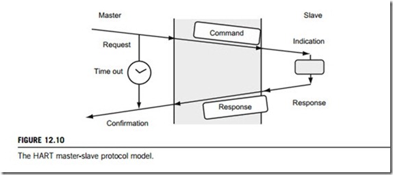
HART communication uses a master-slave protocol, which means that a field device as slave speaks only when it is spoken to by a master. In every communication, a master device sends a command message first; the slave device processes it and then sends back a response message (Figure 12.10). Both the command and response messages include the HART data and must be formatted in accordance with the relevant HCF (HART Communication Foundation) specifications.
The HART protocol can be used in various modes for communicating information between devices, including analog plus digital signals, or digital only signals. Digital master-slave communication together with the 4 20 mA analog signals is the most common. This mode, depicted in Figure 12.10, allows digital information from the slave device to be updated twice per second in the master. The 4 20 mA analog signals are continuous and can still carry the primary variable for control. Please note that when a communication between the master and the slave is engaging, interrupt is definitely not allowed.
A burst is an optional communication mode (Figure 12.10) which allows a single slave device to continuously broadcast a standard HART response message. This mode frees the master from having to send repeated command requests to get updated process variable information. The same HART response message is continuously broadcast by the slave until the master instructs the slave to do otherwise. Data update rates of 3 4 per second are typical in burst-mode communication, but will vary with the chosen command. Please note that the burst mode should be used only in single slave device networks.
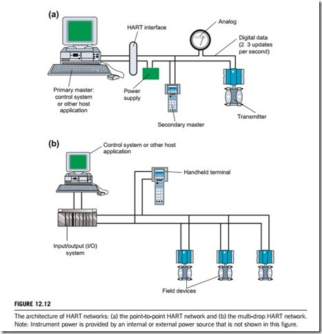
Two masters (primary and secondary) can communicate with slave devices in a HART network. Secondary masters, such as hand-held communicators, can be connected almost anywhere on the network and communicate without disturbing the primary master, typically a PLC, or computer- based central control or monitoring system. A typical installation with two masters is shown in
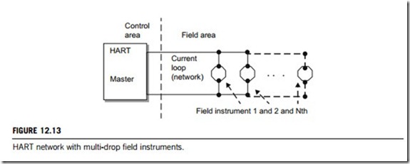
Figure 12.12 and Figure 12.13. From an installation perspective, the same wiring that is used for conventional 4 20 mA analog instruments carries HART communication signals. Allowable run lengths will vary with the type of cable and the devices connected, but can in general be up to 3000 m for a single twisted pair cable with shield, and 1500 m for multiple twisted pair cables with a common shield. Unshielded cables can be used for short distances. Intrinsic safety barriers and isolators which pass the HART signals are readily available for use in hazardous areas.
HART protocol also has the capability to connect multiple field devices on the same pair of wires in a multi-drop network configuration, as shown in Figure 12.12(b). In multi-drop networks, communication is limited to master-slave digital only. The current through each slave device is fixed at the minimum value needed to power the device (typically 4 mA) and no longer has any meaning for the process.
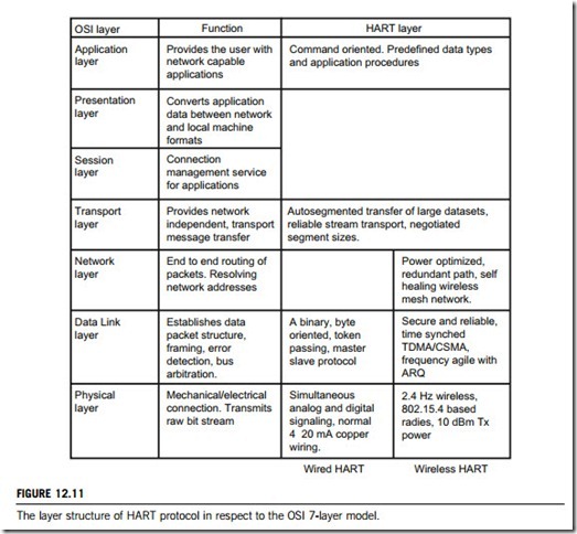
HART protocol utilizes the OSI 7-layer reference model. As is the case for most of the communication systems at field level, it implements only layers 1, 2, and 7 of the model. Layers 3 6 remain empty since their services are either not required or are provided by the application layer 7 (see Figure 12.11).
The application layer defines the commands, responses, data types, and status reporting sup- ported by the protocol. In addition, there are certain conventions in HART (e.g., how to trim the
network current) that are also considered part of the application layer. While the Command Summary, Common Tables, and Command Response Code Specifications all establish mandatory application layer practices (including data types, common definitions of data items, and procedures), the Universal Commands specify the minimum application layer content of all HART-compatible devices.
12.2.2 HART networks
HART communication comprises two folders: communication protocol and connection system. The previous subsection discussed the HART protocol. This subsection focuses on HART networks, and the next subsection will focus on HART devices.
There are two kinds of HART network available in industry: wired and wireless. Obviously, these two kinds of network use different connection media and different communication mechanisms, which therefore support different architectures and require different devices.
(1) Wired HART networks
There are two types of wired HART networks available their architecture is shown in Figure 12.12; the first (Figure 12.12(a)) is a point-to-point network, and the second (Figure 12.12(b)) is a multi- drop network. As shown in the figure, wired HART networks include the host controller and field devices that can be transmitters; between the host and the field devices, this system has an I/O system that can be the system interface with the HART network, and a hand-held terminal or hand- held communicator.
A network with a single field instrument or device that does both HART network functions and analog signaling is probably the most common type in use, and is called a point-to-point network. In some cases, it may have a HART field instrument or device but no permanent HART Master, for example, if the user intends to use mainly analog communication, and the field instrument or device parameters are set prior to system installation. A user might also set up this type of network and then later communicate with the field instrument or device which is using a hand-held communicator (also named HART secondary master). This is a device that clips onto device terminals (or other points in the network) for temporary HART communication with the field instrument or device.
A HART field instrument is sometimes configured so that it has no analog signal, only a HART function. Several such devices can be connected together (electrically in parallel) on the same network, as shown in Figure 12.13, in which case they are said to be multi-drop, and the master is able to talk to and configure each one in turn. When field instruments or devices are multi-drop there cannot be any analog signaling, and the term current loop ceases to have any meaning. Multi-drop field instruments powered from the network draw a small, fixed current (usually 4 mA) to maximize the possible number of devices. A field instrument or device that has been configured to draw a fixed analog current is said to be parked; accomplished by setting the short-form address of the field instrument or device to some number other than 0. A hand-held communicator might also be connected to the network, as displayed in Figure 12.13.
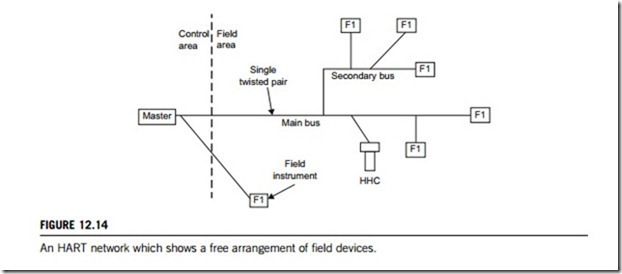
There are few restrictions on building wired HART networks. The topology may be loosely described as a bus, with drop attachments forming secondary buses as desired, as illustrated in Figure 12.14. The whole collection is considered a single network. Except for the intervening lengths of cable, all of the devices are electrically in parallel. The hand-held communicator (HHC) may also be connected virtually anywhere. As a practical matter, however, most of the cable is inaccessible and the HHC has to be connected at the field instrument or device, in junction boxes, or in controllers or marshalling panels. In intrinsically safe (IS) installations there is likely to be an IS barrier separating the control and field areas.
A field instrument may be added or removed, or wiring changes can be made while the network is live (powered). This may interrupt an on-going transaction. However, if the network is inadvertently short-circuited, this could reset all devices. The network will recover from the loss of a transaction by retrying a previous communication. If field instruments or devices are reset, they will eventually come back to the state they were in prior to the reset. No reprogramming of HART parameters is needed.
Digital signaling brings with it a variety of other possible devices and modes of operation. For example, some field instruments or devices are HART-only and have no analog signaling. Others draw no power from the network. In still other cases the network may not be powered (no direct current). There also exist other types of wired HART networks that differ from the conventional one described
here. These are covered in the technical reports and product manuals of the HART network manufacturers.
(2) Wireless HART networks
Wireless HART is the first open and interoperable wireless communication standard that has been designed to address the critical needs of the process industry for reliable, robust, and secure wireless communication.
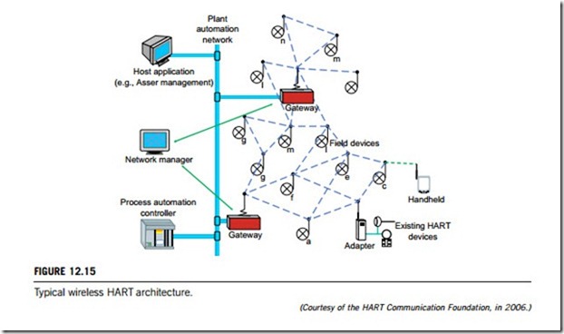
A wireless HART network consists of field devices, at least one gateway, and a network manager, all wireless. These components are connected into a wireless mesh network supporting bidirectional communication. Figure 12.15 shows a typical wireless HART network architecture with only the principal devices plotted, which are as follows:
(1) Network manager
The network manager is the application software that manages the mesh network and network devices. It: (a) forms the mesh network; (b) allows new devices to connect to the network; (c) sets the communication schedule of the devices; (d) establishes the redundant data paths for all communications; and (e) monitors the network.
(2) Gateway devices
The gateway device connects the mesh network with a plant automation network, allowing data to flow between the two network devices. It provides access to the wireless HART devices for a system or other host application.
(3) Network devices
A network device is a node in the wireless mesh network. It can transmit and receive wireless HART data and perform the basic functions necessary to support network formation and maintenance. Network devices include field devices, router devices, gateway devices, and mesh hand-held devices.
(a) Field devices. The field device may be a process-connected instrument, a router, or hand-held device. The wireless HART network connects these devices together.
(b) Router device. A router device is used to improve network coverage (to extend a network), so it is capable of forwarding messages from other network devices.
(c) Process-connected instrument. It is typically a measuring or positioning device used for process monitoring and control; it is also capable of forwarding messages from other network devices.
(d) Adapter. An adapter is a device that allows a HART instrument without wireless capability to be connected to a wireless HART network.
(e) Hand-held support device. Hand-held devices are used in the commissioning, monitoring, and maintenance of network devices; they are portable and operated by plant personnel.
Wireless HART networks can be configured into a number of different topologies including the following:
1. Star network. Star networks have just one router that communicates with several end devices. This is one of the simplest network topologies, appropriate for small applications.
2. Mesh network. Mesh networks are formed by network devices that are all routers. They provide a robust network with redundant data paths, able to adapt to changing radio frequency environments.
3. Star mesh network. These are a combination of the above two.
12.2.3 HART devices
For building and maintaining a HART-enabled system, the technical kernel will be choosing the HART-compatible devices. Devices must be fully compliant with the HART protocol specification, and be tested and registered with the HART Communication Foundation (the HCF).
Devices which support the HART protocol are grouped into master (host) and slave (field) devices. Master devices include communicator or hand-held terminals as well as PC-based workplaces that stay in a control room. Slave devices, on the other hand, include sensors, transmitters, valves, and various actuators.
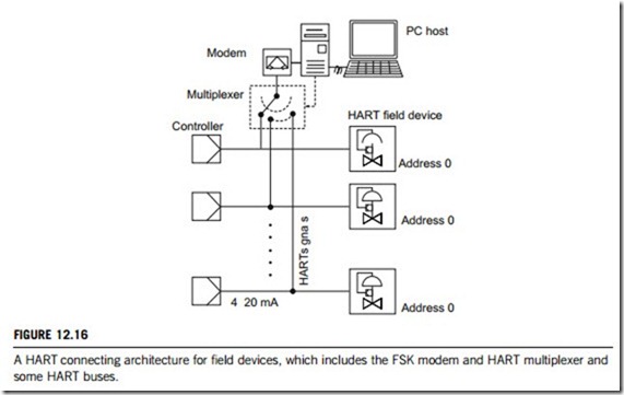
Both master (host) and slave (field) devices have an integrated FSK modem, whereas computers or workstations have a serial interface to connect the modem externally. HART communication is often used for such simple point-to-point connections. Nevertheless, in multi-drop connections, the number of accessible devices can be increased by using a multiplexer and some FSK buses. Figure 12.16 illustrates a multi-drop HART network which has a configuration of the FSK modem, HART multi- plexer, and HART buses.
(1) HART communicator
The HART communicator is the type of communicator most widely used across the world in industrial control systems. They are portable, their weight has been evenly distributed for comfortable
one-handed operation in the field. The result is a universal, user upgradeable, intrinsically safe, rugged and reliable field communicator. In HART-enabled systems, such communicators are often defined by engineers as the secondary master (Figure 12.12(a)) or handheld terminal (Figure 12.12(b)).
Together with a memory and a microprocessor or some application-specific integrated circuits, the HART communicator provides a complete solution for configuring and monitoring all HART and fieldbus devices in an industrial control system.
It is composed of three main components plus accessories. These parts consist of the hand-held; the HART interface hardware, and the application software suite. The communicator runs on a robust, real-time operating system. This trio of hardware and software comprises a complete HART field communicator, which can be powerful, multifaceted, and portable all in one.
The hardware primarily includes the HART interface and associated pinch connectors. The interface is designed to join the multiple connectors located on the bottom of the hand-held device, allowing communication between it and the network. The pinch connectors easily connect to any HART network for instant communication. Most of the interface requires no batteries, running solely off the hand-held’s internal power supply. Its compact size and low power consumption makes the interface very portable.
Its software suite includes some distinctive applications. The main application allows communication, monitoring, and configuration of HART-compatible devices, based upon manufacturer device description files (DDL) and thus allows access to all menus and parameters as designed by the manufacturer. The software allows the logging of device variable values over time. A wide range of variables can be logged automatically at a user-selectable sample time, or manually one by one. These logs can be saved and transferred to a PC for further analysis.
(2) FSK modem
There are often two kinds of modem required in the HART-enabled networks: the USB (universal serial bus) modem and the FSK (frequency shift keying) modem, all connected to the host PC (personal computer). The USB modem is an ordinary PC modem, without special adaptation for HART functions. However, the FSK modem should be particularly designed for HART functions. The following discussion will focus on the FSK modem.
The FSK modem is designed to provide HART communication capabilities for the implementation of frequency shift keying (FSK) techniques for data transfer. It is also required to conform to the HART network’s physical layer. For this purpose, most FSK modems operate to the Bell 202 standard and are made into a chipset containing some integrated circuits. As shown in Figure 12.8, FSK is the frequency modulation of a carrier of digital capability. For simplex or half duplex operation, the FSK modem uses a single carrier in which communication can only occur in one direction at a time. For full duplex, the FSK modem uses multiple carriers for simultaneous communication in both directions.
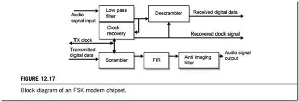
The basic block diagram for the FSK modem chipset is depicted in Figure 12.17, which illustrates the mechanism of data modulation and demodulation. This chip is divided into three main parts: receive, transmit, and clock recovery. Both receive and transmit blocks are separate and data can be processed in each direction independently.
(1) Modulator for transmitting data
The data transmit section of this chipset performs modulation, in which the scrambler makes a nearly flat spectrum output signal, which is connected to a long digital FIR (finite impulse response) filter. This filter compensates for distortion in the transmission line and removes sharp edges a rising from high-low or low-high logic transitions. It makes the transmitted signal spectrum narrow to fit band- width and compensates the signal for the receiver’s side. The transmit wave’s shapes are stored in an EPROM (an electronic memory; refer to Chapter 5 of this textbook). In this way the transmitted waveform is synthesized not only from the present bit’s state, but also from the four that preceded it and the four to come. Data burnt into EPROM represent filter response for each of 256 combinations.
(2) Demodulator for receiving data
At the receiving side, the audio signal going from the discriminator of the transceiver is passed through a low-pass filter to eliminate pertinent higher frequencies, and remove out-of-band spurious noise and
residue. The signal is then limited and detected by sampling at the correct instant. At this point, the detected data, still randomized, are passed through a descrambler, where the original data are recovered and the result goes off to terminal. A descrambler, like a scrambler, simply provides the invert function of the scrambler and perforce requires some numbers of bits to synchronize.
(3) Clock recovery
The heart of the receiver is a digital phase-locked network (DPLL), which must extract a clock from the received audio stream. It is needed to time the receiver functions, including the all-important data detector. Each waveform has a phase shift of 360/256 degrees and is made up of 16 samples. The received audio signal is limited, and a zero-crossing detector circuit generates one cycle of 9600 Hz for each zero-crossing (a proto-clock). This is compared with a locally generated clock in a phase detector based on an up/down counter. The counter increments if one clock is early, decrements otherwise. This count then addresses an EPROM, mentioned above. In this way, the local clock slips rapidly into phase with that of the incoming data. The local clock signal is derived from the output of EPROM. Output data are converted to sine voltage with maximum amplitude.
(3) HART multiplexer
In HART-enabled industrial networks, the multiplexer acts as a gateway between the network management computer and the field devices. Many field devices are distributed over a wide area in industrial process systems, and must be monitored and adapted to changes in the processing environment. The HART multiplexer enables communication between an asset management computer or workstation and the field devices that support the HART protocol, in order to fit into the changes in the process system. All actions on the field device are parallel to the transmission of the 4 20 mA measurement signals and have no influence on the measurement value travelling through the system.
Each HART multiplexer, regardless of whether it is a slave or a master, provides a connection to a specified number of field instruments, allowing thousands of field units to communicate and exchange data with a computer or workstation. Working with a hand-held terminal (HART commu- nicator) is also possible, since the HART protocol allows two masters (computer and hand-held terminal) to exist in one system. Systems can be easily expanded and the advantages of the HART communications can be exploited. Currently, a system can have a maximum of 31 HART multiplexer masters which are linked to the computer with an RS-485 interface. Each HART multiplexer master controls up to 15 HART multiplexer slaves.
(4) HART connecting buses
HART-enabled networks require several kinds of buses to connect devices and instruments. A brief description of two of these buses is given below.
(1) Bus for split-range operation
In industrial process systems, there are special applications which require that several (usually two) actuators receive the same control signal. A typical example is the split-range operation of control valves, in which one valve operates in the nominal current range from 4 to 12 mA, while another uses the current range from 12 to 20 mA. In this type of operation, control valves are connected in series in the network. When both valves have a HART interface, the host device must be able to determine which valve it must communicate with. To achieve this, the HART protocol revision 6 (1999), and beyond will be extended by one more network variant. As is the case for multi-drop mode, each device is assigned to an address from 1 to 15. The analog 4 20 mA signals preserve its device-specific function, which is, for control valves, the selection of the required travel.
(2) FSK bus
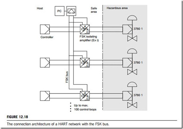
The HART protocol can be extended by the FSK bus. Similar to a device bus, this can connect approximately 100 HART-compatible devices, and address these devices at the present technical level. This requires special assembly-type isolating amplifiers (e.g., TET 128). The limit on the number of participants is because each additional participant increases the signal noise lowering signal quality beyond the point that the telegram can be properly evaluated. The HART devices are connected to their analog current signal and the common FSK bus line with the isolating amplifier (Figure 12.18). From the FSK-bus viewpoint, these amplifiers act as impedance converters enabling devices with high load to be integrated into the network. To address these devices, a special, long form of addressing is used. During the configuration phase, the bus address and the tag number of each device are set with the point-to-point line. During operation, the devices operate with the long addresses. In this way, the system configuration can be read and checked during the start-up phase.
(5) HART system interface
HART communication can only function properly when all participants can interpret the HART signals correctly. To ensure this, not only must the transmission lines fulfil certain requirements, but also the devices in the current network must not impede data transmission. This is because the inputs and outputs of these devices are specified only for the 4 20 mA technology, and, as the input and output resistances change with the signal frequency, such devices are likely to short-circuit the higher- frequency HART signals (1200 2200 Hz).
Where a HART communication system is connected with other kinds of communication systems, gateways could be the best devices for protocol conversion. In most cases, when complex commu- nications must be performed, fieldbus systems are preferred. Even though there is no complex protocol conversion, the HART-enabled system is capable of communicating over long distances, and the signals can be transmitted over telephone lines using HART/CCITT converters, in which the field devices directly connect to dedicated lines owned by the telephone company. However, as already mentioned, the HART-compatible field devices also require an appropriate communication interface that could be, for example, an integrated FSK modem or a HART multiplexer.
HART signals are imposed on the conventional analog current signal, whether devices are designed to use the four-wire or the two-wire technique. However, it is important to note that the maximum permissible load of a HART device is limited by the HART specification. Another limitation is due to the process controller, which must be able to provide the power for the connected two-wire device.
The higher the power consumption of a two-wire device is, the higher is its load. The additional functions of a HART communicating device increase its power consumption, and hence its load. When retrofitting HART devices into an existing installation, the process controller must be checked for its ability to provide the power required by the HART-compatible device; i.e., at least the load impedance of the HART device at 20 mA.
