Bode Diagram
Bode diagram is an alternative way of presenting the frequency response of open loop transfer function. The amplitude ratio in decibels is plotted against frequency in logarithmic scale. On the same diagram or on separate diagram underneath the amplitude ratio curve, the phase angle is also plotted against the frequency in logarithmic scale. A typical Bode diagram is shown in Fig. 2.15.
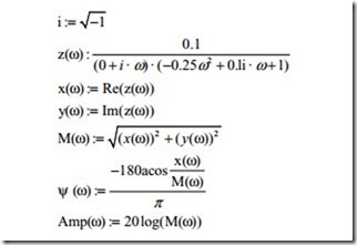
The phase angle reaches – 270° for a third order transfer function as frequency is in- creased. The graph of Fig. 2.15 shows that the phase angle reaches – 180° and then the phase angle is reduced. This is because the acos function only supports 180 and – 180°. The phase angle above –180° minus the reduction from –180°. The absolute phase angle is above –180°. To find the direction of phase angle it is better to study the real and imaginary values as shown below the equations used to plot the Bode diagram.
The gain margin and phase margin as defined in Nyquist plot can be obtained from Bode diagram. This is for a stable system. If the amplitude ratio curve intersects the 0 db line below the 0 db line when the phase angle is – 180°, the closed system is unstable. The Bode diagram shown in Fig. 2.12 gives the gain margin as 12 db. And the phase margin is obtained as the difference between – 180° line and the actual phase angle when the amplitude ratio is 0 db. This is 90° for the system shown in Fig. 2.13.
It should be noted that the plot of frequency response of open loop transfer by hand is very tedious. It is easy always to write a simple computer program to plot Nyquist or Bode diagram. There is also commercial software to plot the above- mentioned diagrams.
The Nyquist and Bode diagrams are the frequency response of the open loop transfer function. At each frequency, the open loop response is a complex number. Equation (2.7) can be used to calculate the frequency response of the closed loop system. There are graphical methods of obtaining the closed loop frequency re- sponse from the open loop frequency response. By the advent of computers, these methods are not recommended.
The above analysis forms the basis of analysis of control systems. In the fol- lowing examples, the analysis of some simple and complicated systems will be covered. This includes some mechanical and electrical systems that find application in servo motor systems.
Example 2 simple spring.
A simple linear and rotational spring is shown in Fig. 2.16. The relationship be- tween the force F and displacement x assuming a linear relation can be written as
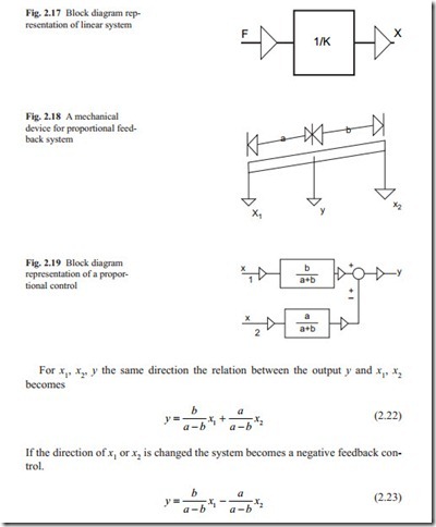
This relation, assuming the force F as input and displacement x as the output is shown in block diagram form in Fig. 2.17. The output displacement x responds instantly when a force F is applied. The term 1/ K is a zero order transfer function.
Example 3 Addition or subtraction of two signals.
Figure 2.18 shows a mechanical device that can be used to add or to subtract two signals. The system consists of a mechanical bar with three possible movements.
The above equations in block diagram form are shown in Fig. 2.19. The arrows show the direction of signal flow.
Example 4 Mass–Spring–Damper system.
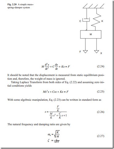
A simple mass–spring–damper system is shown in Fig. 2.20. The input is usually force and the output is the displacement. Writing equation of motion the relation between displacement and force becomes,
As was discussed in Chap. 1, the response characteristic is completely described by ωn, ζ and the system always remains stable but could be overdamped or under- damped.
Example 5 Gears.
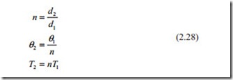
When two gears are in contact, usually the input θ1 is considered as input and the output is θ2 (Fig. 2.21). If the diameter of input gear is d1 and the diameter of output gear is d2, then the following relations about speed ratio n and torque can be written.
Figure 2.21 shows the correct direction of the parameters defined in Eq. (2.26).
Example 6 Electronics devices for achieving proportional, derivative, integral, and lead-lag action.
There are electronics devices that can be used to achieve proportional, integral, and derivative action. These devices are known as Operational Amplifiers or in short OP-AMP. The purpose of this book is not to describe the circuit designs but to give brief description of their behavior when included in a control system. An OP-AMP is shown as a triangle, which shows the direction of flow of signal (Fig. 2.21).
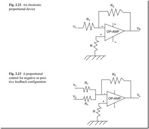
Figure 2.22 shows an amplifier and a proportional control with OP-AMP. There are two inputs one positive and negative. The negative pin is used for input signal. The other + and − signs shown on the side of OP-AMP are the power supply pins. The exact construction of the circuit diagram is usually shown in the manufacturer data book.
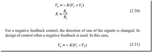
For an amplifier, the output voltage is obtained by multiplying the input signal by a factor K. That is,
It should be noted that an OP-AMP changes the sign of the signal and for positive gain two of them must be used in cascade. For positive and negative feedback con- trol, they can be wired as shown in Fig. 2.23.
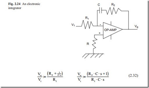
When a capacitor is attached to the feedback loop of an operational amplifier, it becomes an integrator (Fig. 2.24).
If R2 is selected as zero then the OP-AMP becomes a pure integrator.
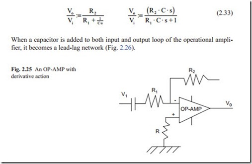
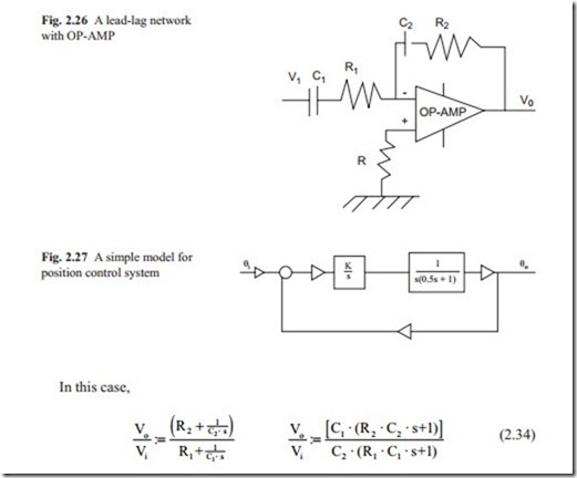
When a capacitor is attached to input side of an OP-AMP, it becomes a derivative and with the addition of a resistor in the input loop, the OP-AMP becomes a derivative plus a lag network, which is often used to reduce the noise, and usually amplified in the derivative action (Fig. 2.25).
To find the gain of an OP-AMP, the impedance of the feedback loop must be divided with the input impedance. Doing this gives
Often it is desirable to increase the gain of a feedback control systems so to increase the speed of response and to reduce steady state error. When the gain is increased, the systems move towards instability. To overcome this problem, the Proportion- al + Integral +derivative, (PID) control network may be used. The problem is to ad- just the three parameters of the PID. The derivative action always amplifies the noise present in the system. In this case, a lead-lag network is preferred.
Example 7 A servo position control.
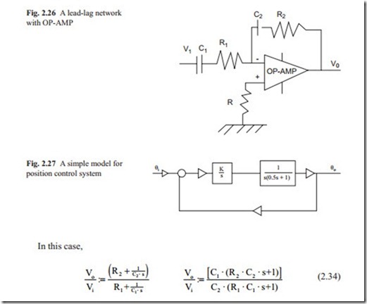
The simplest model for a position control system with separately excited DC motor is shown in Fig. 2.27. In the loop, there is a lag network because of the rotor inertia and there are two integrators. One to convert velocity to position and one to achieve zero steady state error. This will be discussed in detail in the proceeding chapters.
The closed loop transfer function can be obtained as
where θo, θi are the output and the required position respectively. The stability of the system can quickly be checked by Routh–Hurwitz method. The array can be built up as shown below,
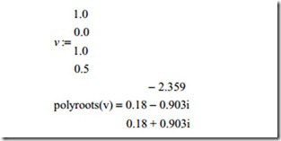
There are two sign changes in the first column and it shows that the system is un- stable for all values of K. It also shows that there are two roots in the right hand side of the complex plane. This method is an easy method for checking the stability of control systems but it does not show how oscillatory the system is if it is stable. The MathCAD or other control software can be used to calculate the roots of character- istic equation. In MathCAD program, a vector ( v) is defined in which the first ele- ment should be the constant and with the coefficients of the characteristic equation. Then the statement polyroots ( V) gives the roots. In this method, the gain can be changed to see how roots move in the complex plane. The root locus can be plotted if required. Otherwise the gain is varied so that all roots lie between the + 45 and the − 45° lines and they are located as far as the origin possible so that the system responds quickly with minimum amount of oscillation. If the system is unstable as the case is in this example compensation network must be used to stabilize the sys- tem with acceptable transient response. For this example, the MathCAD program is used to calculate all roots for various values of K. For example, for K = 1, the vector v is defined as
It can be seen that there is a real root with negative value and there are two complex values with positive real part indicating that the above characteristic with the value of gain defined is unstable. In fact, the above process can be repeated to show that for all values of the gain the system is unstable. The table below shows the roots for some values of gain.
In fact, the process can be repeated to plot the root locus if required. It can be seen that all roots move towards infinity. The real root moves on the negative real axis towards infinity and the two complex roots, which always appear in conjugate move towards infinity on the right hand side of the s-plane. In fact, there are always the same amount of loci as the order of the characteristic equation. If there are zeros in the open loop transfer function, some loci tend to move towards these zeros; other- wise they move to infinity.
Example 8 Servo with velocity feedback.
As was shown in the previous example, position control systems with two integrators inherently are unstable. To introduce damping and to stabilize the system, a velocity feedback is added. The derivative term always introduces noise in the system. In practice, a small DC motor known as tacho generator is attached to the motor, which produces a voltage proportional to velocity of the motor. This is shown in Fig. 2.28.
The closed loop transfer function can be obtained as
The right hand side of the denominator is known as the open loop transfer function. It shows that with the addition of the velocity feedback, a zero appears that attract the unstable roots. Therefore, the system becomes more stable. Simplifying Eq, (2.36) gives
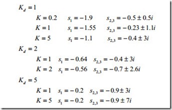
Similar to the previous example, the MathCAD software is used to find the roots of the characteristic equation for various values of k and kd. The result is summarized below;
The value of Kd has been changed first so that the zero of the open loop transfer function remains unchanged as K is changed. It is clear that the poles of the open loop transfer function move towards the zero and infinity as both parameters are changed. The response usually dominated by the roots that are nearer to the imaginary axis. For small values of Kd, the complex roots dominate the response and the system becomes oscillatory.
For large value of Kd, the real root becomes dominant and the response becomes very slow. When Kd = 2, K = 2 the real part of the real root and imaginary root are very close together and these values are suitable for the system. As will be shown later, the gain of the system must be selected as large as possible so that the steady state error becomes smaller. In this example, there are three roots and two param- eters to change; so it is not possible to locate the three roots as it is wished on the s–plane. In the next chapter, it will be shown that with state variable feedback it is possible to locate the roots anywhere in the s–plane. The only limitation will be the noise and saturation limit present in practical transducers and amplifiers.
