VALVES, REPLACE
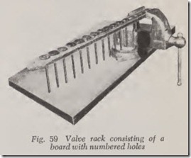
If a numbered rack is not available to receive the valves as they are removed, one can be made by drilling enough holes in a board to accommodate them, Fig. 59. This is not essential when valve faces and seats are to be reconditioned and valve guides replaced. But when valve guides are still serviceable and not removed, each valve should be returned to its own guide because the extent of wear between one guide and another may vary enough to cause trouble later on if valves are switched. Then, too, exhaust valves are often made of greater heat resisting material than are intake valves. In most cases, however, intake valve heads are larger in diam eter than exhaust valve heads, in which case switching them would readily be noticed since they would not seat in the head or block properly.
L-Head Valves, Remove
fnasmuch as only 6-cylinder L-head and the Willys 4-cylinder L-head engines are currently in use the following material pertains to them.
Take off the cylinder head and valve covers.
Clean the valve chambers. Cover any openings in the floor of the valve chambers with clean cloth or cardboard so that the valve locks will not fall into the crankcase as they are removed.
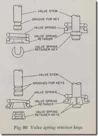
The valve spring retainer is locked to the valve stem by means of a lock or key. Some keys are U shaped although most are split in two halves. Both types are shown in Fig. 60. The key must be re moved in order to remove the spring and valve.
The key is readily removed after the valve spring is compressed.
First remove the valves and springs from those valves which are closed. Then, turn over the en gine until anoth er group of valves close and then remove them. Continue to rotate the engine in this manner to close the remaining valves and remove them.
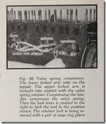
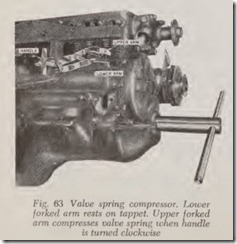
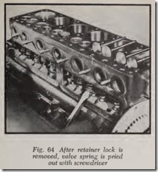
Valves are removed with the aid of a spring compressor, Figs. 61, 62, 63. Compress the spring sufficiently so that the retainer lock can be re moved. Release the compressor so that the spring can expand. Remove the valve and then take out the spring, Fig. 64. Remove the rest of the valves and springs in like manner, being sure to place them in the valve rack in the proper sequence, Fig. 59.
In case a valve refuses to come out, it may be removed with the tool shown in Fig. 65. The claw of the tool is slipped under the head of the valve and the sliding hammer is banged up against the nut, breaking the valve loose from its guide.
L-Head Valves, Install
Befor e installing valves, be sure they are per fectly clean. Coat the valve stems with light en gine oil. When installing a spring, do not compress it any more than necessary to insert the retainer key as too much compression may permanently shorten its length and thus weaken the spring action.
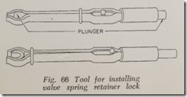
There are a number of tools for inserting the retainer locks. Fig. 66 shows one design. The retainer lock is placed in the jaw end of the inserter. Then, while the valve spring is com pressed, the retainer lock is slipped up over the end of the valve stem. When the lock is in the correct position, the plunger on the handle end of the inserter is pushed inward to eject the lock and at the same time the spring compressor is released so that the spring presses down on the retainer and “seats” the retainer lock.
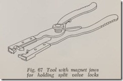
Fig. 67 illustrates an inserting tool which has permanent magnet jaws to grip the two halves of the retainer lock.
Ford & Mercury V-as (1949-53)
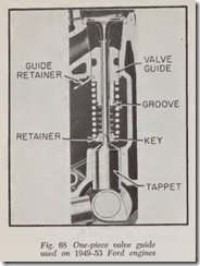
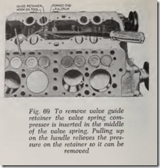
Fig. 68 shows the valve assembly used on these engines. The valve guide has a forked retainer while the valve spring retainer at the tip of the stem is equipped with a split valve lock. The valve assembly is removed as a unit by means of the forked lever which engages the groove in the lower end of the valve guide, Fig. 69.
Overhead Valves, Remove
There are various types of tools for compressing the valve springs but the type most generally used is the C-shaped design, Fig. 70. The forked jaw is applied to the valve spring seat and then the screw plunger is turned clockwise until it touches the head of the valve. Pushing the operating han dle compresses the spring and permits removal of the retainer lock.
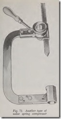
Another design of a C-shaped tool is shown in Fig. 71. The hollow hex is placed against the valve spring seat. The knurled knob is turned left to release the pointed square shaft. The point is brought into contact with the head of the valve and the knurled knob is locked by turning it to the right or clockwise. Then the handle is moved clockwise to compress the spring.
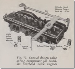
Special valve tools of different designs are made for modern overhead valve V-8 engines, each de signed espPci811y for a particular engine. Fig. 72 illustrates the one for Cadillac. The tool is placed on the bench and the cylinder head is placed on the frame of the tool with the va lves touching the valve supports. The arm is aligned with the valve spring as shown and then the sprin g is com pressed by the foot inserted in a stirrup.
Overhead Valves, Install
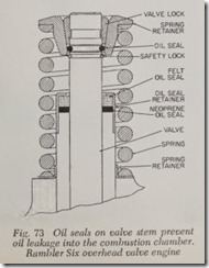
On most modern overhead valve engines, oil seals are used on the valve stems to pr event the seeping of oil into the combu stion chambers. On the Rambler Six shown in Fig. 73 there are three seals. There is a round seal near the upper end of the valve stem and there is a dual seal at the top of the valve guide. There is also a neoprene seal which prevents excessive passage of oil and above it is a felt seal which provides valve stem lubrica tion during the initial starting period.
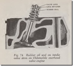
A number of modern overhead valve engines have a round rubber oil seal near the upper end of the intake valve stem to prevent und ue leakage of oil down the stem and into the engine, Fig. 74. Other overhead valve engines have similar oil seals to provide this protection.
When new seals are installed, they should be checked with a small suction cup which is placed on top of the valve spring retainer. If there is no leakage the cup should stick in place.
CARBON CLEANING
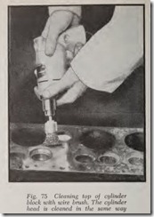
After the valves have been removed, all the parts should be thoroughly cleaned of carbon and any other deposits. The work may be done with a small putty knife and a wire brush with a handle, obtainable in a hardware store, or with a wire scraper. However, electrically-driven brushes are faster and more thorough. Fig. 75 shows the type of brush used for cleaning the top of the cylinder block.
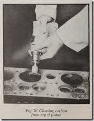
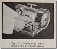
To clean the top of a piston, use the brush shown in Fig. 76 but first move the piston until it is inch below the top of the block.The valve stem and valve head should be cleaned either with a hand brush or with the rotary brushes shown in Figs. 75, 76, while the valve is held in a vise; or better yet, clean the valve with a rotary brush on a bench grinder, Fig. 77.
After cleaning the valve it is a good plan to polish the upper half of the stem with a fine emery or crocus cloth (about 300 grit). The polishing can be done by hand while the valve is held in a vise or the valve may be rotated in a valve re facing tool. In either case use a narrow strip of cloth. Hold the two ends in the fingers to form a half loop around the valve stem.
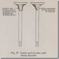
Sometimes layers of lead oxide and carbon will build up on the exhaust valve stem just below the head, Fig. 78. This deposit is baked into a very hard substance. The deposit may extend far enough down the stem to interfere with the clos ing of the valve.
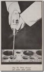
Valve stem guides should be cleaned by means of the wire cleaner shown in Fig. 79. This cleaner can be operated by hand if an electric drill is not available. It is moved up and down in the valve guide while it is being rotated.
If the upper end of the valve guide is counter bored be sure that the counter bore is thoroughly cleaned.
After all surfaces have been cleaned of carbon, wipe them with a cloth or use an air nozzle to blow away any remaining particles of carbon. Be careful to blow out all bolt holes in which carbon dust may have settled. This remark applies par ticularly to cylinder bolt holes. If one of these holes becomes partially filled with carbon it will prevent full tightening of the bolt when it is replaced.
Rice is used to remove carbon from engine combustion chambers without taking off the head in a process developed by Oldsmobile. Called the “Head-On” Carbon Blaster, this device utilizes specially prepared rice, under air pressure, di rected through the spark plug openings.

