Jeep Overhead Camshaft Engine
Removal
1. With camshaft sprocket removed, lift rocker arm guide from cylinder head.
2. Check rocker arms to determine which do not have cam tension against them. Turn these parallel to camshaft.
3. Temporarily install camshaft sprocket on camshaft and rotate camshaft to release tension from remaining rocker arms. Tum these parallel to the camshaft also. Continue to do this until all rocker arms are out of engagement with the camshaft.
4. Remove two nuts that attach camshaft retainer to cam bearing support deck and remove retainer.
5. Pull forward on camshaft to remove it from cam bearing support deck.
6. Remove cam bearing support deck from cylinder head.
Inspection
Clean the camshaft thoroughly with a suitable solvent. Make sure all oil passages are free. Check the cams for scoring or wear. The cam face must be perfectly smooth throughout their contact areas. Runout of the camshaft, measured with a dial indicator at the intermediate bearing journals, must not exceed .0005″.
Check the camshaft journal diameters with a micrometer. The specified diameters are as fol lows:
| Front | 1.9965-1.9975″ |
| No.2 | 1.8715-1.8725″ |
| No.3 | 1.7465-1.7475″ |
| Rear | 1.3715-1.3725″ |
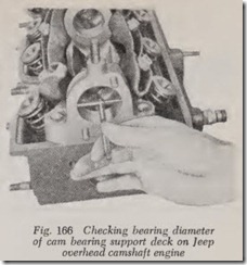
Check the cam bearing support deck for cracks or distortion . Check the bearing surfaces of the cam deck for visible wear or scoring. Using a telescope gauge and micrometer, check the in ternal diameters of the cam bearing deck bearings
as shown in Fig. 166. The specified diameters are as follows:
| Front | 1.9995-2.0005″ |
| No.2 | 1.8745-1.8755″ |
| No.3 | 1.7495-1.7505″ |
| Rear |
1.3745-1.3755″ |
Compare each journal diameter with the corre sponding bearing diameter. If the bearings are defective or permit more than .04″ running clear ance, the cam bearing deck and/ or the camshaft must be replaced, Fig. 167.
Installation
1. Install cam bearing support deck on cylinder head. Torque nuts to 15-20 ft-lb.
2. Lubricate bearing with engine oil and care fully slide camshaft into bearing support deck from the front, being careful not to damage bearin gs in support deck or journals on cam shaft.
3. When camshaft is fully seated, install retainer on front of support deck.
Pontiac Tempest Overhead Camshaft Engine
Removal
1. Remove camshaft sprocket and seal as outlined previously.
2. Remove rocker arm cover.
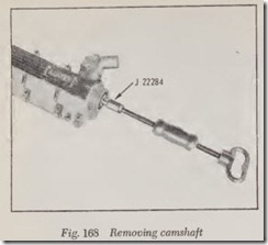
3. Using tools of the type shown in Fig. 168 drive camshaft from rocker cover. Caution: Do not allow camshaft to damage bearing surfaces of rocker cover.
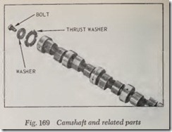
4. Remove parts shown from rear of camshaft, Fig.169.
5. Remove water outlet fitting and thermostat from rocker cover.
6. Clean all parts and inspect for wear or damage. Minor nicks or scratches on edge of bearing surface can be corrected with a suit able scraper or file.
Installation
1. Install camshaft into rocker cover.
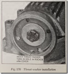
2. Install thrust washer, Fig. 170.
3. Install retaining bolt and washer and torque to 40 ft-lbs.
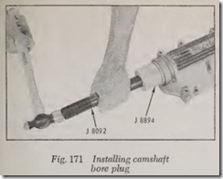
4. Using a tool of the type shown in Fig. 171, drive plug in so it is fully seated. Note: A camshaft bore plug not fully seated could result in excessive camshaft end play which is .003″ to .009″ when read at the sprocket end with a dial indicator.
5. Replace water outlet fitting and thermostat.
CAMSHAFT BEARINGS, REPLACE
The installation of new camshaft bearings is not a common operation. They have comparatively light loads to carry as compared with crankshaft bearings. Therefore if the camshaft bearings are properly lubricated )Vith clean oil they will usually last for the life of the engine.
If, for some reason, the camshaft bearings do not receive sufficient oil they may burn out, that is, the bearing surface may melt and thus be ruined, in which case new ones will be required.
Also, if examination with a narrow feeler gauge shows that the clearance is .006″ or more, new bearings are called for-if satisfactory valve ac tion and valve life are to be obtained.
If the engine has been removed from the ear for an overhaul, it is desirable to install new camshaft bearings if the clearance exeeeds .0035″ or .004″.
Various tools are made for removing and replac ing camshaft bearings, but usually they consist of piloted drifts to pull out the bearings and to push them in place. However, in one ease a jaw-type puller is used for the removal of the rear camshaft bearing.
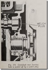
The rear camshaft bearing rests in a hole in the eylinder block which must be sealed at the rear to prevent oil leakage. A bolted-on plate is some times used although on most engines a disk of metal with a slight crown is driven into the hole, Fig. 172, and thus expanded. The disk is called a weleh plug or expansion plug. Onee the camshaft is removed the plug can be driven out so that the rear bearing may be removed.
If an oil leak should develop at the plug it ean be pried out after drilling or punching a hole in its center and then a new one ean be driven into place.
Camshaft Bearing Tools
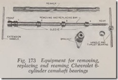
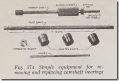
Each ear manufacturer makes available to its dealers special tool sets to remove and install camshaft bearings together with instructions on how the set is used. Fig. 173 illustrates the tool set designed especially for Chevrolet 6-eylinder en gines, and Fig. 174 shows the set furnished for Chrysler engines. In general they all work in the same manner. However, for the reader’s informa tion we will describe the operation of the Chrysler tool set which, incidentally, ean be used on a number of non-Chrysler engines.
Before describing the use of this equipment there are two things to remember: ( 1) The adapter pilots must be just the right size for the earnshaft bearings they are to be used on. ( 2) Regardless of which bearing is being removed or replaced all three pilots should be in place, two of
the pilots being used to align the pilot shaft while the third pilot is used to remove or replace the bearing. Each pilot has two diameters. The larger diameter fits the bearing bore while the smaller diameter fits the bearing. Theref ore the pilots ean be used for aligning the pilot shaft either with the bearings in place or removed.
Bearings are removed one by one and likewise are replaced one by one. The tool is rea dy for use when the pilot shaft is screwed into the nut on the hammer shaft. To remove the rear bea ring, for example, in a four-bearing engine, inst all adapter pilots with large diameter to rear in bearings No. 2 and 3, to provide alignment for the tool. Then insert the tool through these bearings and then through No. 4 bearing. Install the remaining adapter pilot with its small diameter pointing forward and then slip the horseshoe washer into the rear slot. The rear bearing is rea dy to be removed (to front) by pounding the sliding ham mer against the striking nut.
Remove No. 3 bearing in the same w ay after plaeing adapter pilots in bearings No. 1 and 2. To remove No. 2 bearing plaee one adapter in this bearing and then place the large diameters of the other two adapters in No. 3 and 4 bea ring bor es. The procPdure for removing No. 1 b earing is similar.
SELECTING A HIGH PERFORMANCE CAMSHAFT
Overcamming an engine is a eommon problem . If your interests lie in building a “street” only maehine, concentrate on moderate increases in net valve lift. Net valve lift is the actual amount the valve lifts off its seat, measured in thousandths of an inch. Depending on engine displacement, a eam with durations from 260°-300° should im prove volumetric efficiency at street speeds. The “duration” of a cam is the actual peri od the valve is off its seat, expressed in degrees of crankshaft rotation. The big problem is one of selectin g th e proper earn for the engine and the specific driving conditions. Generally speaking, earns with mild or medium amounts of duration and overlap should be used with ears equipped with automatic trans missions. “Overlap” is the period of the en gine eyele when both intake and exhaus t valves are open together, measured in erankshaf t degrees .
Street/strip ears offer a little more flexibility in earn selection than do strictly street machin es. Again, depending on engine displaeement, look for net lift figures of from .500″-.515″ and dura tions extending a bit beyond 300°.
For all-out competition, the field is wide open.
Net valve lift can reach as high as .600″ with duration exceeding 330°.
Camshaft Installation Tips
When replacing a stock cam with a high perfor mance cam, always replace related components such as lifters, push rods, rocker arms, valve springs and spring retainers, etc. This insures that the proper relationship between camshaft and valve train components is maintained Never install a cam dry. Always use additional lubricant on wearing surfaces of the cam, tappets and other valve train components. Much of the cam’s wear comes within the first few minutes of operation. Lubrication will prevent this when the engine is started for the first time. Most manufac turers specify or recomm end use of a particular type of lubricant.
The timing chain and gear should always be replaced to help insure proper cam timing. Extra precautions should be tak n when installing and tightening the camshaft sprocket, since high speed vibrations can cause bolts to loosen.
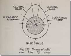
Never use old lifters on a new cam and do not use solid lifters on a hydraulic cam. Hydraulic lifters do not require clearance ramps as do solid lifters, Fig. 175.
Checking Valve-to-Piston Clearance
Always check for ample clearance betwe.en the valves and piston head, particularly when mstall ing a cam with increased net lift. If the prop r clearance is not maintained, it could result m severe damage to the engine through the valves hitting the pistons. To check the clearance,_ lay small soft strips of clay across the top of the p1st n near the valves. With the cam, valves, valve tram and cylinder head gasket installed, bolt the head
into place, and hand turn the engine throu h h:o complete revolutions of the crankshaft. This will insure that both valves in each cylinder move through their complete cycle of operations. Re move the head and measure the thickness of the impressions left by the valves in the clay. In many engines, a clearance of .060″-.080″ minimum is sufficient, but Ford calls for a minimum valve-to piston clearance of .120″. This operation should only be performed after the camshaft has been properly timed. Variations in cam timing or in the amount of valve lash can materially alter the piston/valve relationship. Clearance che king be fore the camshaft is timed is a waste of hme. And it is a must operation whenever any engine modi fication is carried out which could alter the piston/valve relationship. Such modifications in clude: camshaft changing or regrinding; head and block milling; and increasing compression ratios by changing head gasket, crankshaft, rods or pistons.
A simpler method of measuring valve-to-piston clearance, although probably not quite so accurate can be carried out as follows:
1. Bring piston No. 1to TDC on its compression stroke and adjust valve to correct clearance.
2. Rotate crank 360°. This will place both valves in their overlap position (lightly off their seats).
3. Place a dial indicator on top of valve spring retainer, or use a mechanic’s scale beside the spring.
4. Wedge a small pry bar under the rocker arm and depress the valve until it touches the piston. Read the dial indicator or mecha ic’s scale and compare to net valve lift specifi cation. Repeat the procedure for each cylinder.
![Fig.-167-Camshaft-and-bearing-suppor[2] Fig.-167-Camshaft-and-bearing-suppor[2]](http://machineryequipmentonline.com/electric-equipment/wp-content/uploads/2020/06/Fig.-167-Camshaft-and-bearing-suppor2_thumb.jpg)
