Application
DC motors are used in applications where variable speed and strong torque are required. They are used for cranes and hoists when loads must be started slowly and accelerated quickly. DC motors are also used in printing presses, steel mills, pipe forming mills, and many other industrial applications where speed control is important.
Speed Control
The speed of a DC motor can be controlled by applying variable voltage to the armature or field. When full voltage is applied to both the armature and the field, the motor operates at its base or normal speed. When full
voltage is applied to the field and reduced voltage is ap- plied to the armature, the motor operates below normal speed. When full voltage is applied to the armature and reduced voltage is applied to the field, the motor operates above normal speed.
Motor Construction
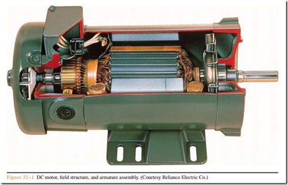
The essential parts of a DC motor are the armature, field windings, brushes, and frame (Figure 32– 1).
The Armature
The armature is the rotating part of the motor. It is constructed from an iron cylinder that has slots cut into it. Wire is wound through the slots to form the
windings. The ends of the windings are connected to the commutator, which consists of insulated cop- per bars and is mounted on the same shaft as the windings. The windings and commutator together form the armature.
Carbon brushes, which press against the commuta- tor segment, supply power to the armature from the DC power line. The commutator is a mechanical switch that forces current to flow through the armature wind- ings in the same direction. This enables the polarity of the magnetic field produced in the armature to remain constant as it turns.
Armature resistance is kept low, generally less than 1 ohm. This is because the speed regulation of the motor is proportional to the armature resistance. The lower the armature resistance, the better the speed regulation will be. Where the brush leads extend out of the motor at the terminal box, they are labeled A1 and A2.
Field Windings
There are two types of field windings used in DC motors: series and shunt. The series field is made with a few turns of large wire. It has a low resistance and is designed to be connected in series with the armature.
The terminal markings, S1 and S2, identify the series field windings.
The shunt field winding is made with many turns of small wire. It has a high resistance and is designed to be connected in parallel with the armature. Since the shunt field is connected in parallel with the armature, line volt- age is connected across it. The current through the shunt field is, therefore, limited by its resistance. The termi- nal markings for the shunt field are F1 and F2.
